Another Differential
Back when I built the nifty spur gear differential for my electric tricycle, I chose to buy, well, spur gears rather than bevel gears like differentials traditionally use. I did this partly because McMaster's spur gears are much cheaper than their bevel gears, and partly because I had the great LOLriokartdiff off which I could base my design.
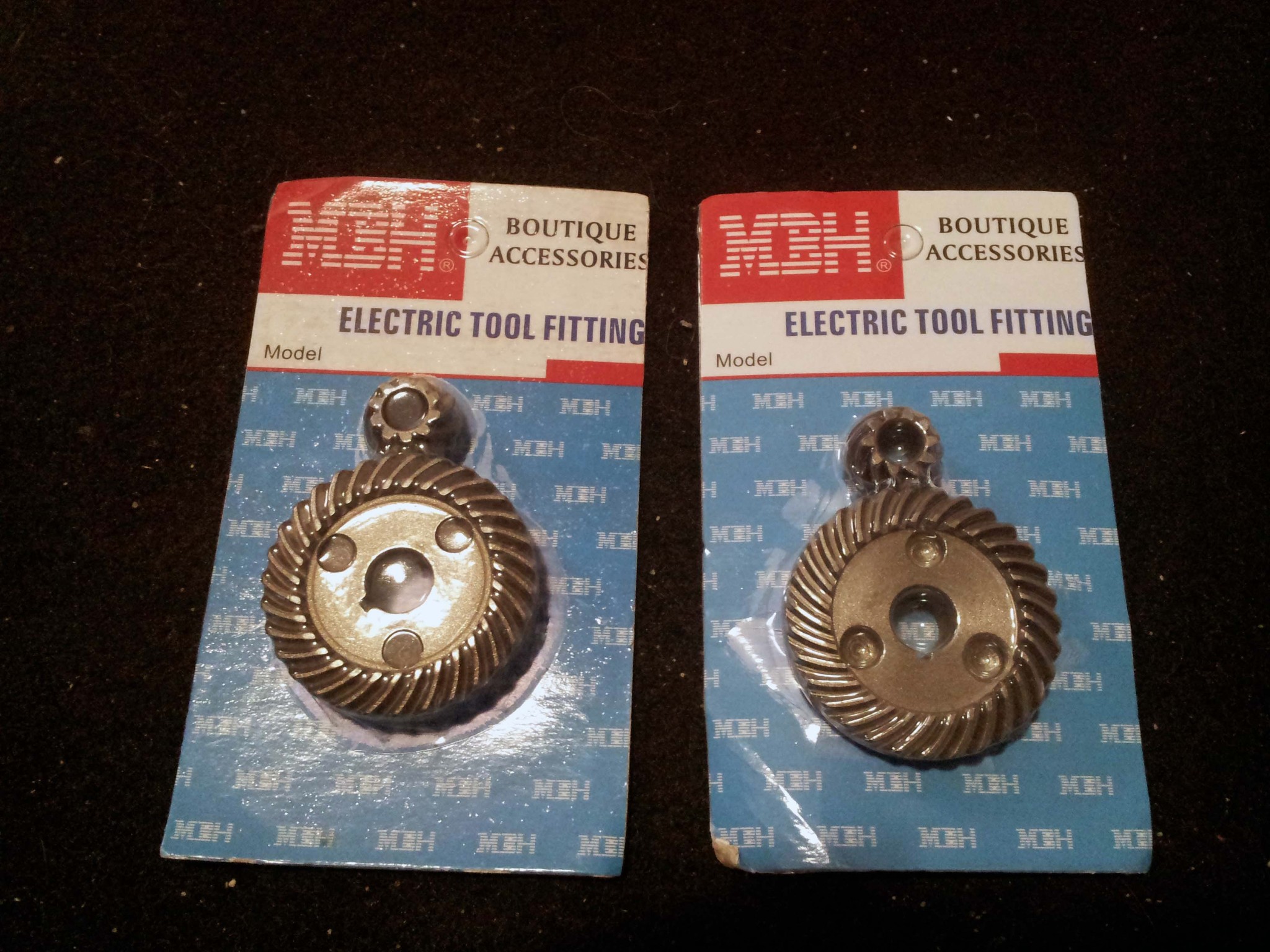
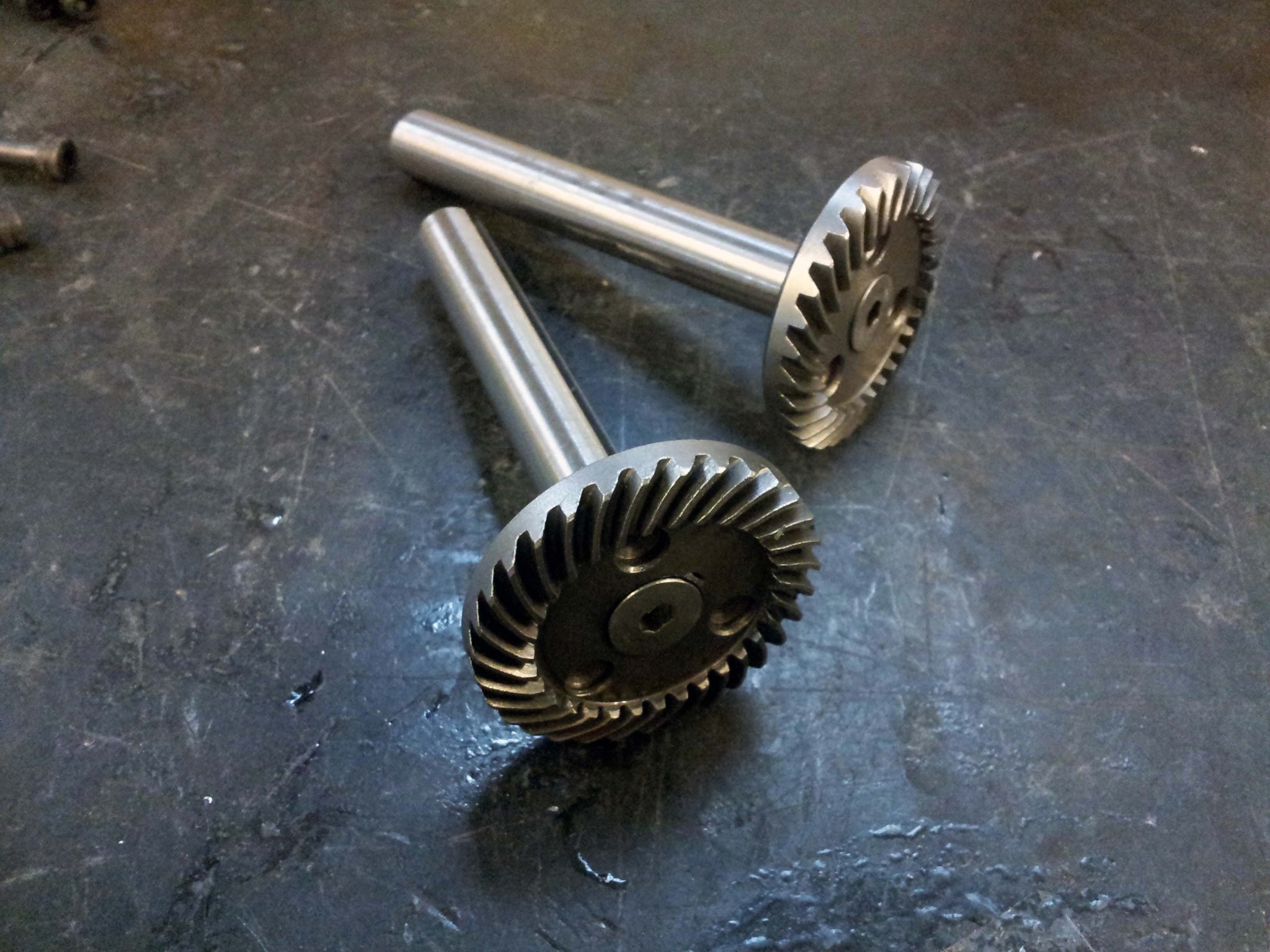
A couple weeks ago, while reading through a build thread on RoboWars Australia I found pictures of some bevel gear sets originally intended for angle grinders, which were purchased from Ebay. A quick search revealed that a number of Amazon retailers stock similar gears. I ended up getting two sets of these, so I could find out how useful they were.
A few days ago, these came in the mail:
First impression: They are very small. The big one is ~1.8" diameter. I didn't measure the pitch, but it looks pretty similar to the 20 pitch spur gears I used in the trike differential. They're almost certainly sintered, so don't know if I'd trust them to withstand a melonpower.
In a differential, they would be assembled roughly like this:
I spent the better part ofnight morning machining the housing for the differential. Because of laziness and oh god randomly sized helical bevel gears, I decided to not bother trying to CAD anything. I basically just found some chunks of aluminum and winged it.
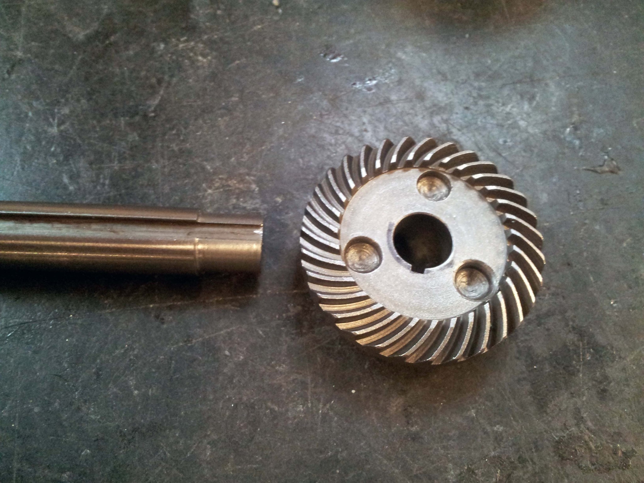
For output shafts I used some 1/2" keywayed shaft left over from my original differential. Since the gears were bored out to 11mm, I turned a shoulder into the shafts.
The gears have some ground down keyway stock stopping them from rotating independently of the shaft, and a big countersunk bolt stops them from moving axially.
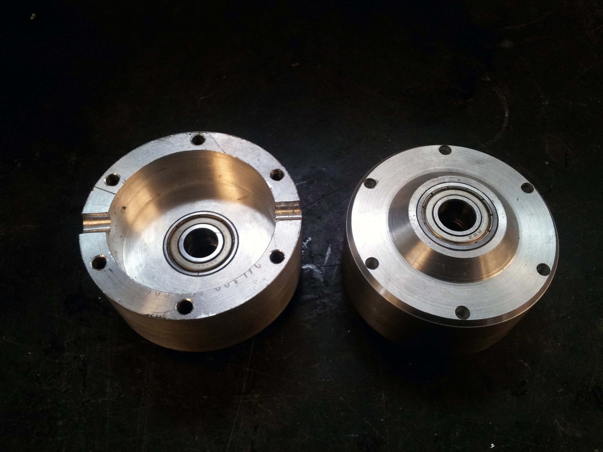
To make the housing, I started with some absurdly large timing belt pulleys that were basically solid aluminum round about 3.4-4" thick by 3" long. The housing is composed of two parts, that are identical except for the six holes. One side has clearance holes for 8-32 screws, while the other side is tapped. The cylindrical grooves in each half retain a 8 mm shaft that goes all the way through, and holds the smaller gears. I made the grooves by bolting the housing together with some paper shims separating the halves, and then drilling holes sized exactly for the shaft. When the shims are removed, the shaft gets squeezed between the two halves, since the groove profiles are not quite full semicircles.
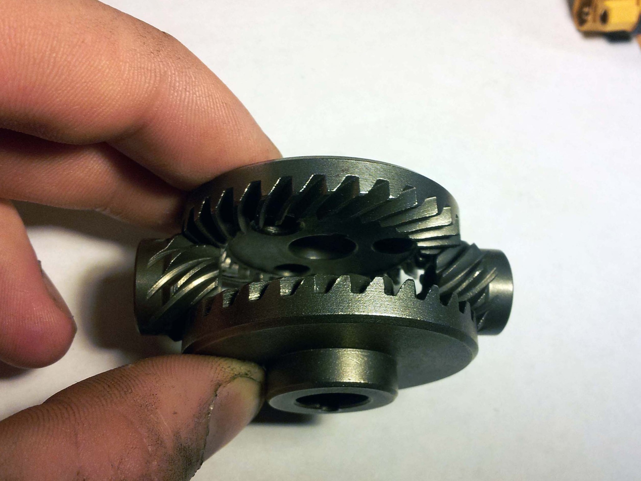
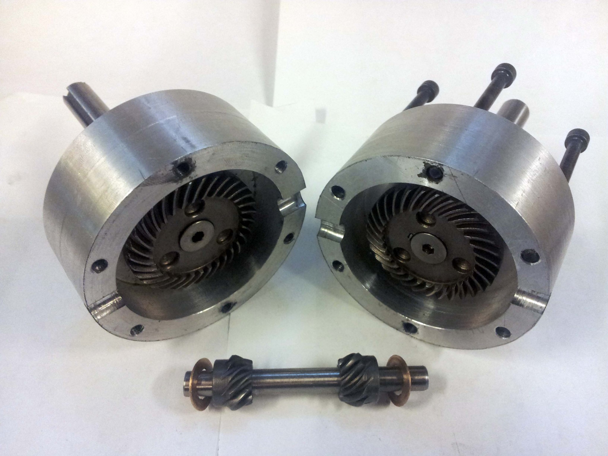
All the parts of the differential laid out:
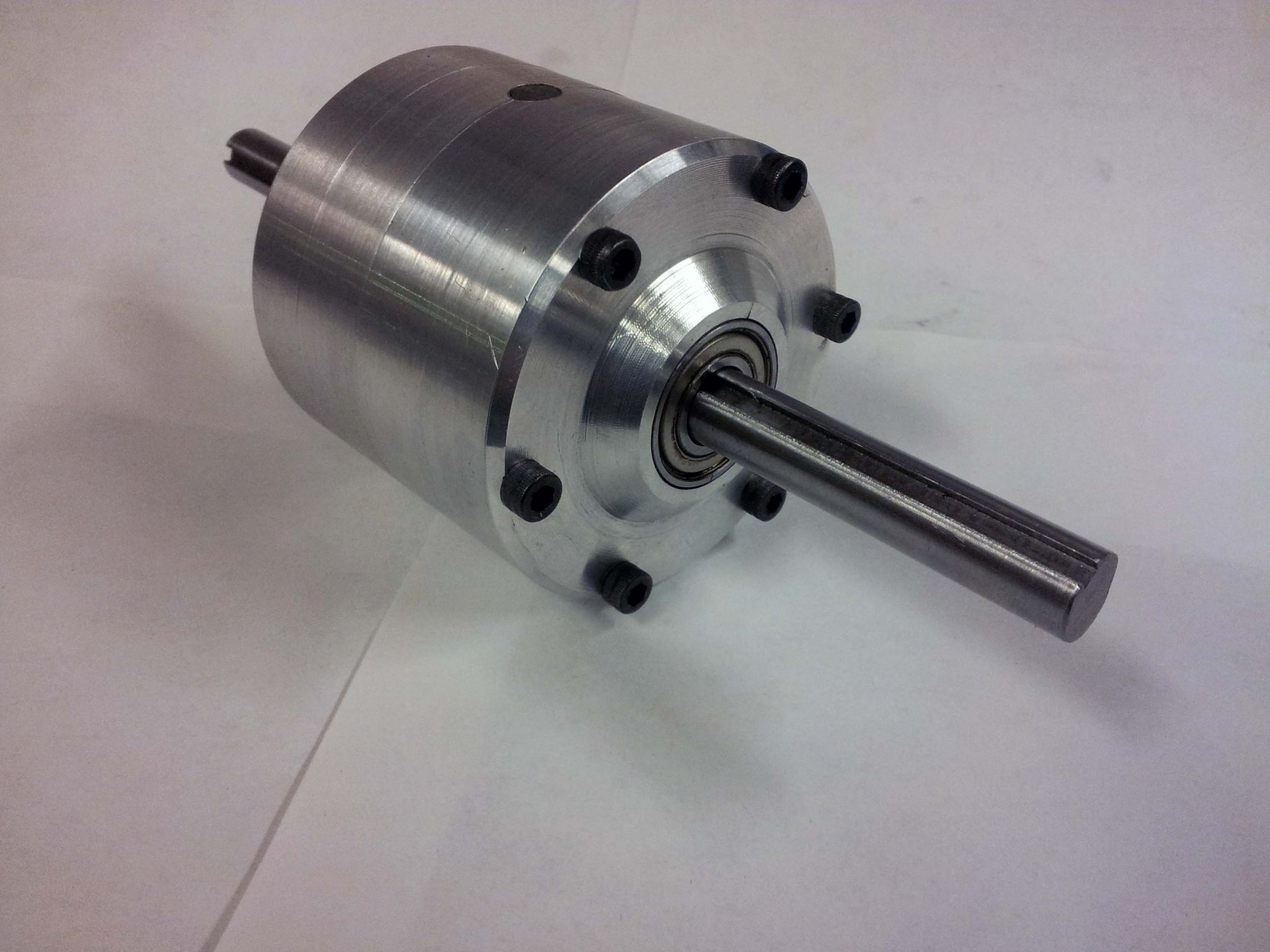
All together. To drive it, you would just bolt a sprocket or pulley through the same six bolts that hold everything together.
I sealed it up with a bunch of grease on on the gears. And you know what? Despite my lack of planning, it works beautifully. Sure, there is a little bit of axial play in the output since I bored out the housing to the wrong depth, but that can be fixed with a washer or two. Also, the steel-on-steel interface between the shaft and two small gears is definitely questionable. The motion is significantly smoother than the spur gear differential, and there is absolutely no binding. It is also a bit more radially symmetric than the spur gear differential, so it should work better at high RPMs, since it won't shake everything apart. Which may be very important, depending on which of the few ideas I have for this I end up going with.
A couple weeks ago, while reading through a build thread on RoboWars Australia I found pictures of some bevel gear sets originally intended for angle grinders, which were purchased from Ebay. A quick search revealed that a number of Amazon retailers stock similar gears. I ended up getting two sets of these, so I could find out how useful they were.
A few days ago, these came in the mail:
First impression: They are very small. The big one is ~1.8" diameter. I didn't measure the pitch, but it looks pretty similar to the 20 pitch spur gears I used in the trike differential. They're almost certainly sintered, so don't know if I'd trust them to withstand a melonpower.
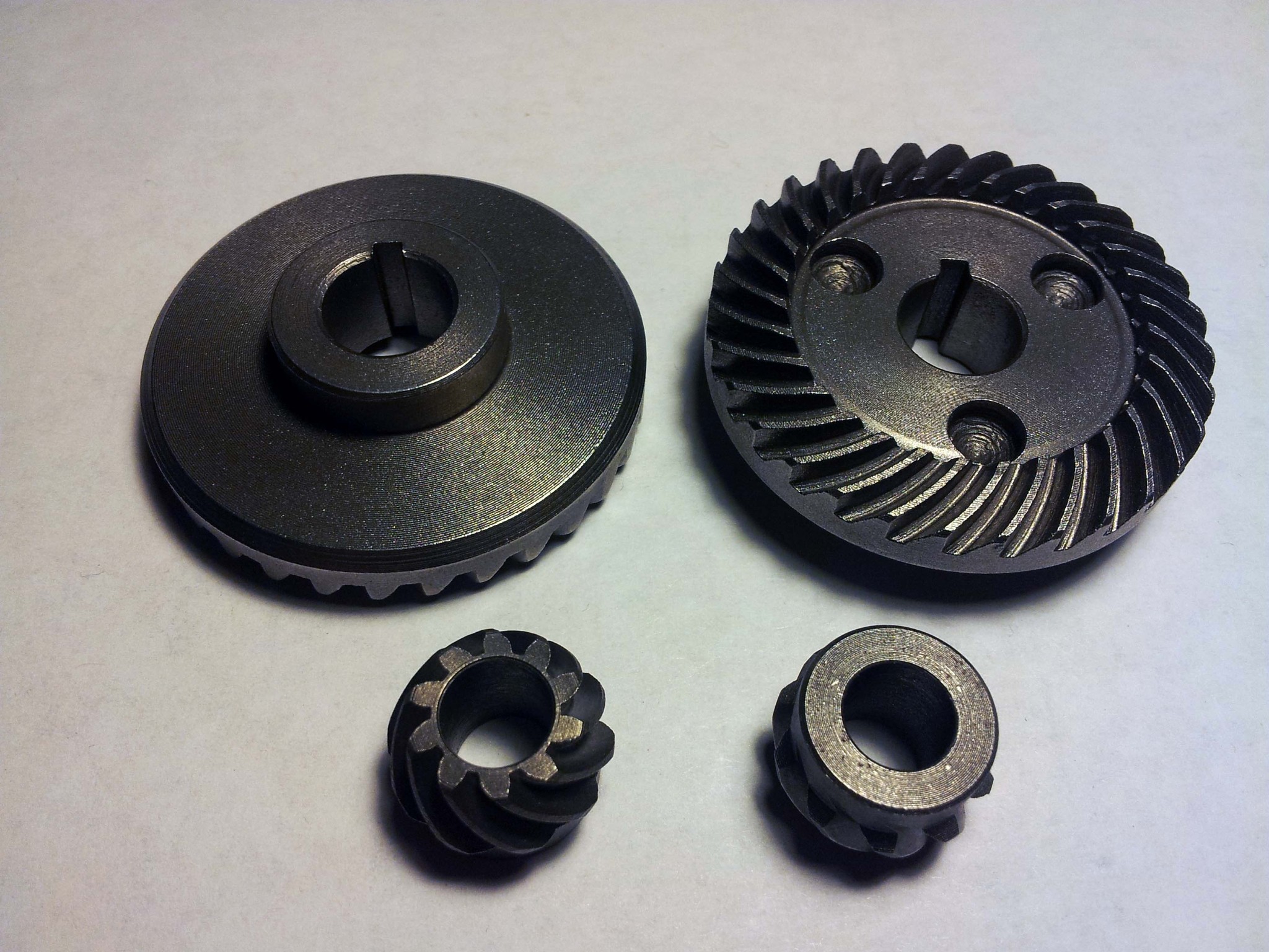
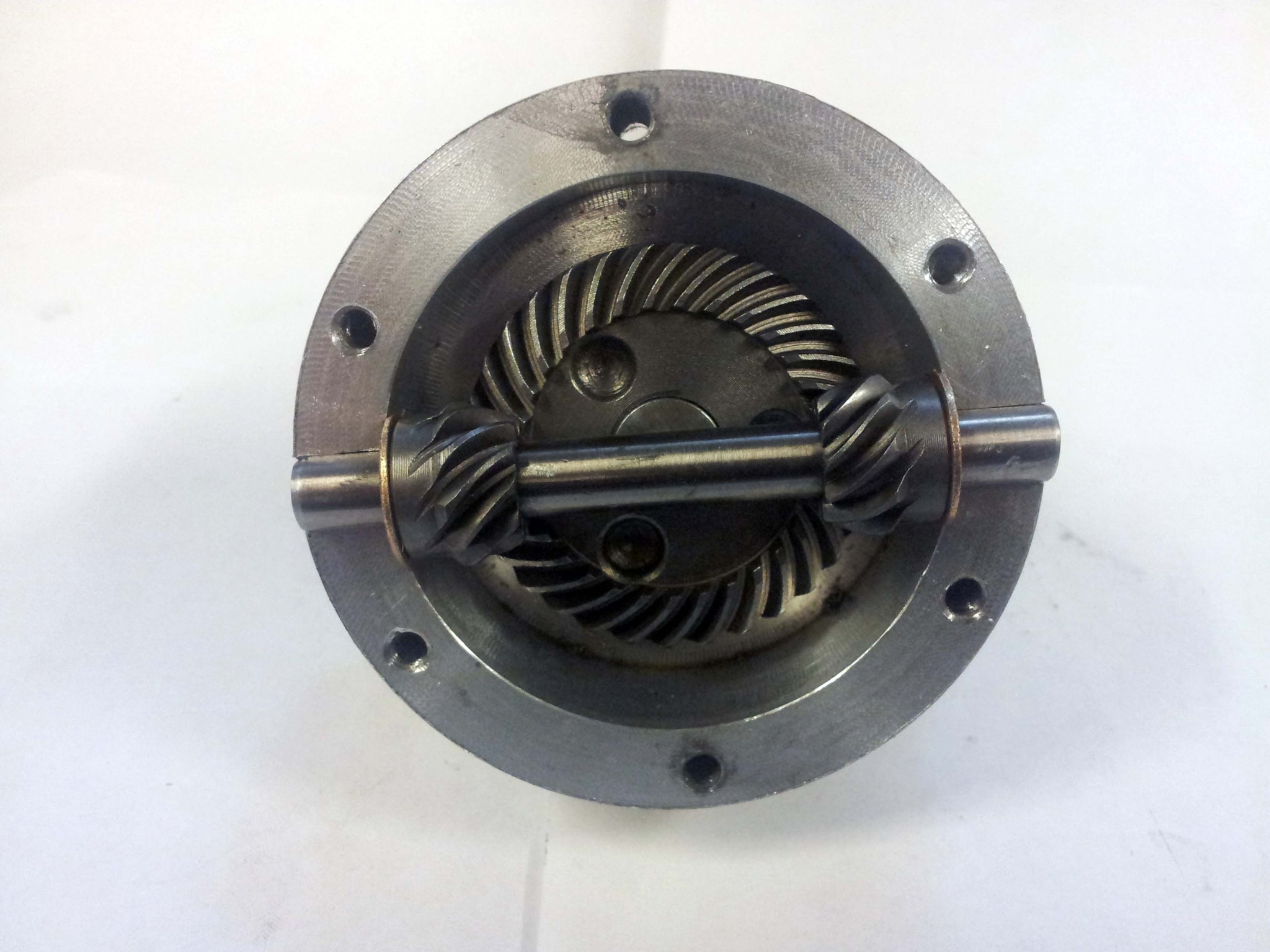
In a differential, they would be assembled roughly like this:
I spent the better part of
For output shafts I used some 1/2" keywayed shaft left over from my original differential. Since the gears were bored out to 11mm, I turned a shoulder into the shafts.
The gears have some ground down keyway stock stopping them from rotating independently of the shaft, and a big countersunk bolt stops them from moving axially.
To make the housing, I started with some absurdly large timing belt pulleys that were basically solid aluminum round about 3.4-4" thick by 3" long. The housing is composed of two parts, that are identical except for the six holes. One side has clearance holes for 8-32 screws, while the other side is tapped. The cylindrical grooves in each half retain a 8 mm shaft that goes all the way through, and holds the smaller gears. I made the grooves by bolting the housing together with some paper shims separating the halves, and then drilling holes sized exactly for the shaft. When the shims are removed, the shaft gets squeezed between the two halves, since the groove profiles are not quite full semicircles.
All the parts of the differential laid out:
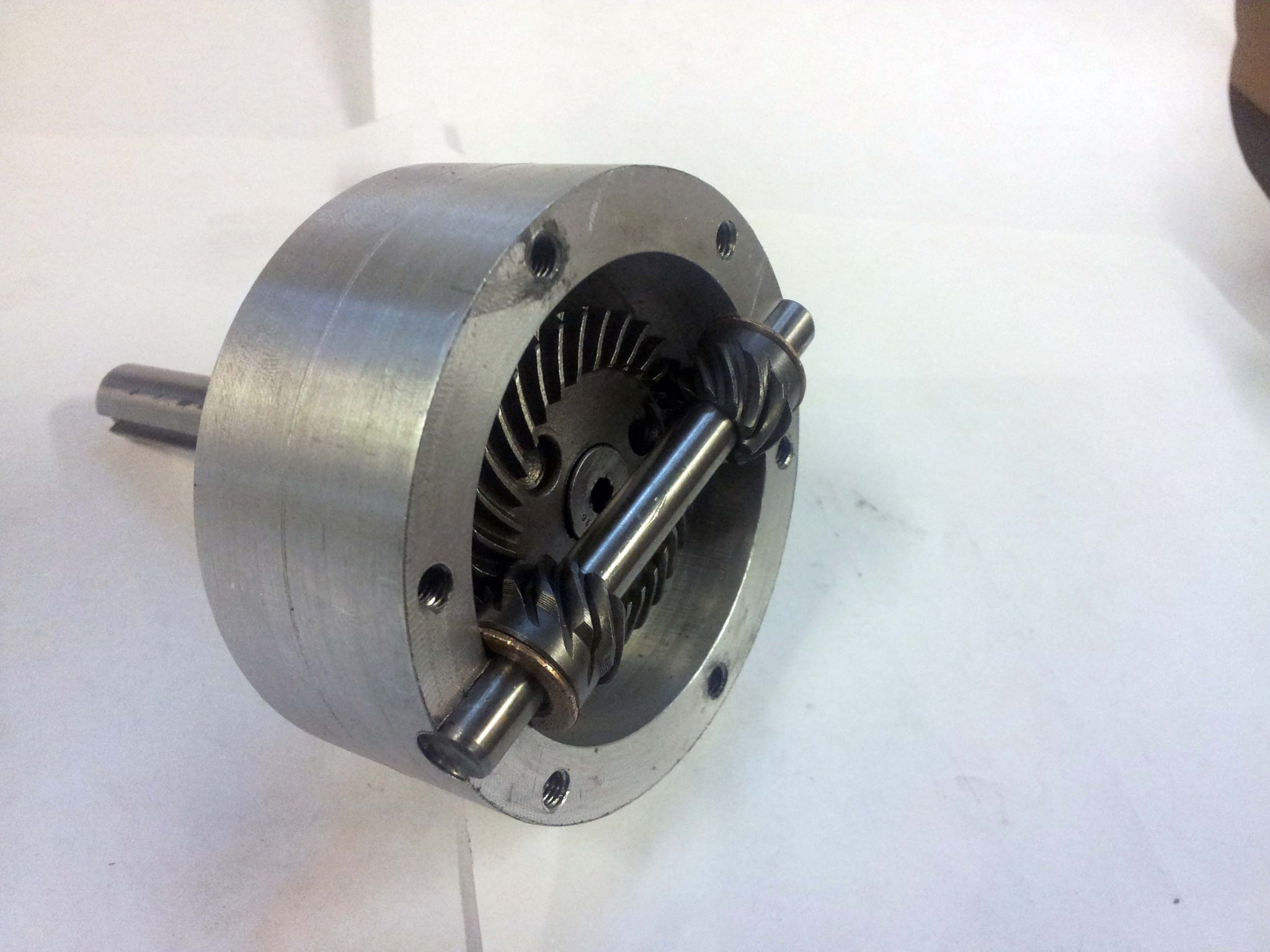
All together. To drive it, you would just bolt a sprocket or pulley through the same six bolts that hold everything together.
I sealed it up with a bunch of grease on on the gears. And you know what? Despite my lack of planning, it works beautifully. Sure, there is a little bit of axial play in the output since I bored out the housing to the wrong depth, but that can be fixed with a washer or two. Also, the steel-on-steel interface between the shaft and two small gears is definitely questionable. The motion is significantly smoother than the spur gear differential, and there is absolutely no binding. It is also a bit more radially symmetric than the spur gear differential, so it should work better at high RPMs, since it won't shake everything apart. Which may be very important, depending on which of the few ideas I have for this I end up going with.
Comments