Closed Loop Espresso Intro
Even before getting a lever espresso machine, I've been thinking about how I might design one if I were to do it from scratch.
This is the layout I've converged to:
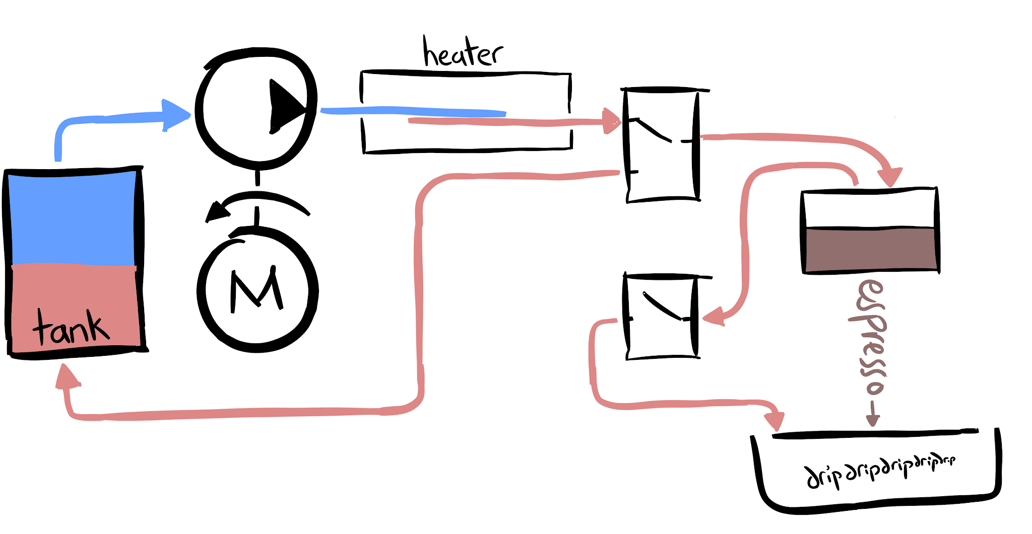
The basic summary is:
- Electric motor driven pump pumps water through a heater.
- If the water at the output of the heater isn't up to temperature, the 3-way valve after the heater will cycle the water back through the tank.
- Once the water at the output of the heater is up to temperature, the valve switches and water is piped over to the group head and coffee.
- An extra "drain" valve between the group head and the drip tray relieves pressure after the shot is done. Strictly this isn't necessary, but it serves a few purposes I'll get into later.
Critically with this setup, the whole tank of water doesn't have to get hot as it would in a boiler-based espresso machine. I'm hoping to get the delay between powering the machine on and pulling the first shot down to a minute or less. With a standard 15A mains outlet, it should be possible to real-time heat over 5 mL/s of water from room-temperature to espresso temperature, so main delay is in getting the thermal mass of the heater up to temperature.
The pump:
As far as I can tell, most "real" espresso machines use either vibratory pumps or rotary vane pumps. From a pure performance perspective these don't seem like great solutions to me. Vibratory pumps are noisy and hard to control (not saying you can't, Decent does pressure control with vibratory pump), and their main appeal is they're cheap and you can plug them straight into mains. Rotary vane pumps are positive displacement (which is good for pressure control, roughly speaking), but tend to have large displacements - meaning for a given pressure, a lot of torque is needed at the input, since (ignoring losses) \(energy = torque*angle = pressure*displacement\). Lots of torque = large motor or gear reduction. However, the pumping power requirements for making espresso are tiny - on the order of a few watts of \(pressure*flow rate\) (9 Bar * 4 mL/s is 3.6 watts, and I think that's towards the upper end of espresso flow rates). So a pump with a small displacement and a tiny motor (effectively getting "gear reduction" through the pump) makes more sense to me.
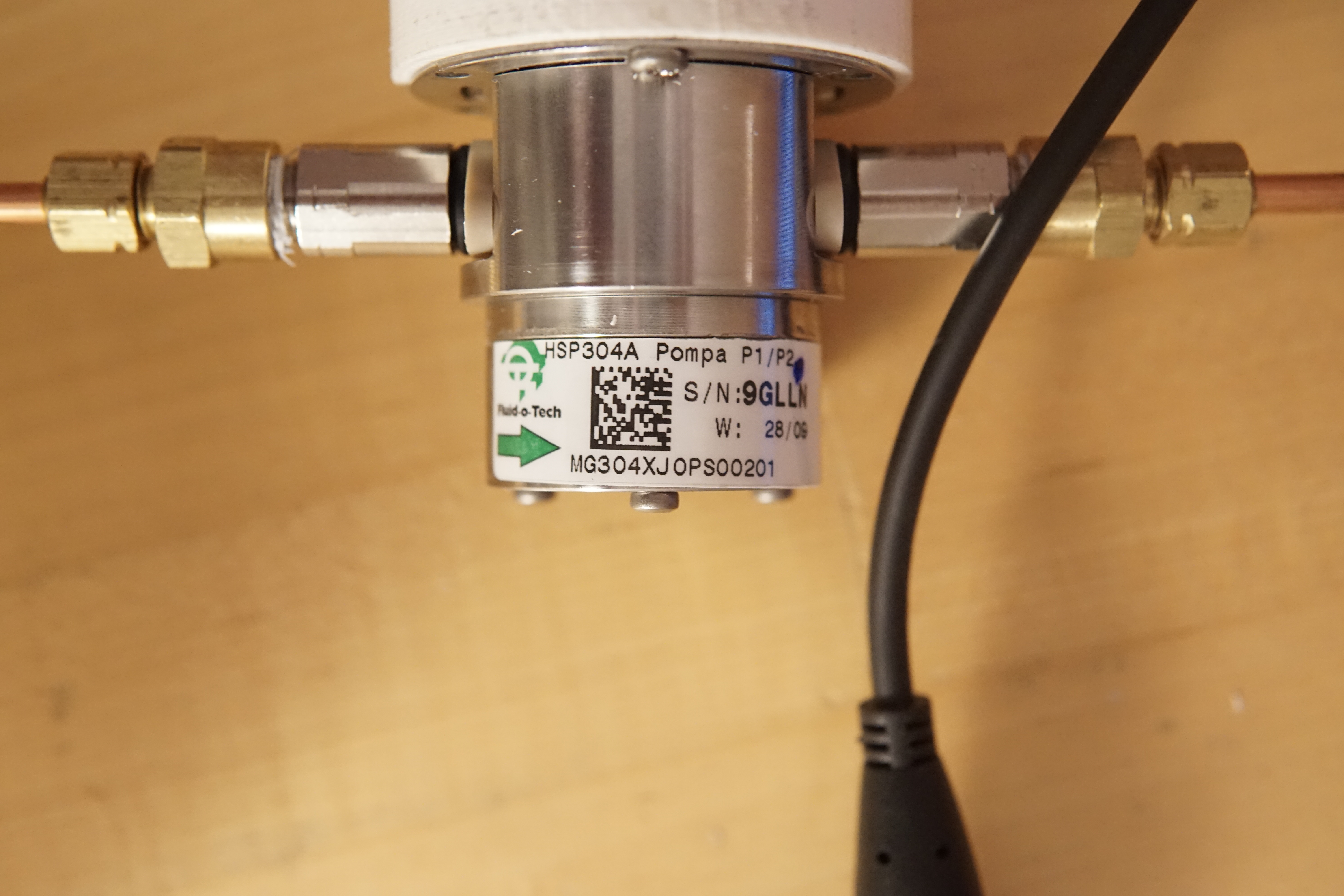
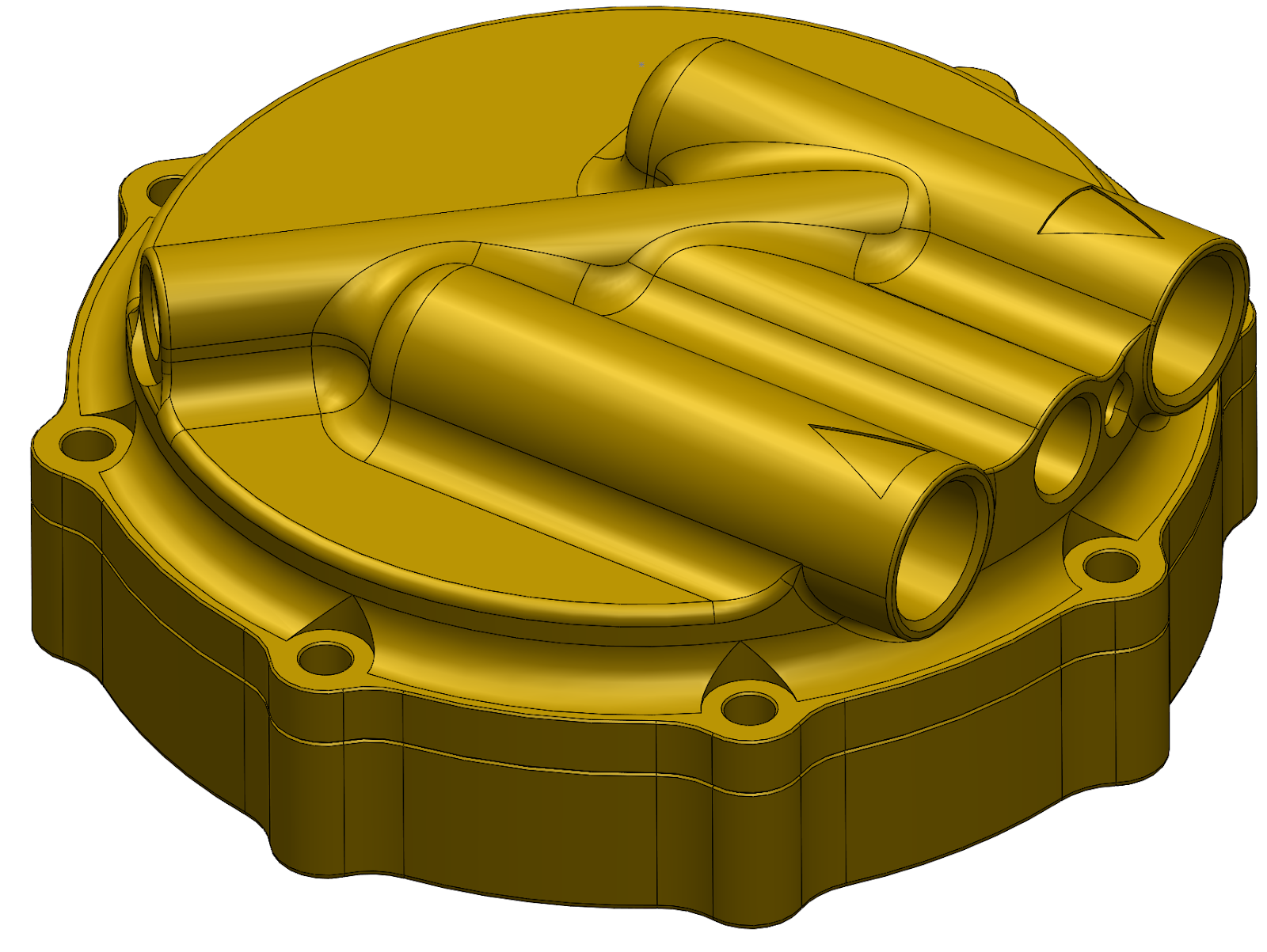
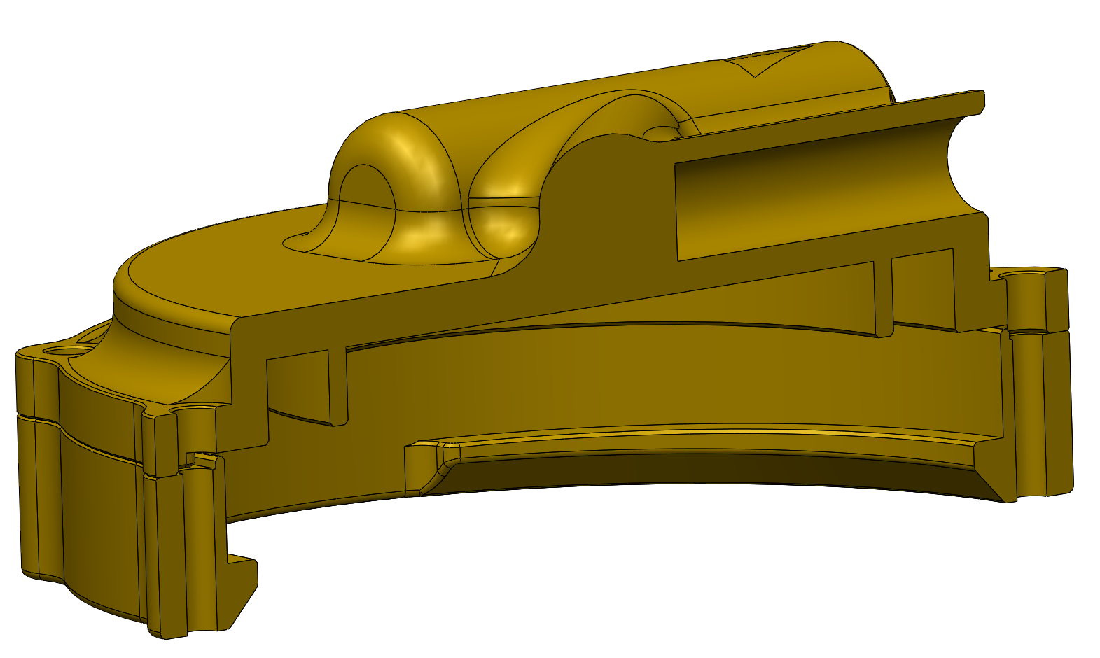
Gear pumps were my first though. What I wanted was "stainless steel body gear pump with PEEK gears", and it turns out that exactly this object exists and can be purchased on ebay for a few tens of dollars. Even better, they all are magnetically coupled, so there are no shaft seals to leak. A couple weeks later I had a Fluid-o-Tech MG304 pump.
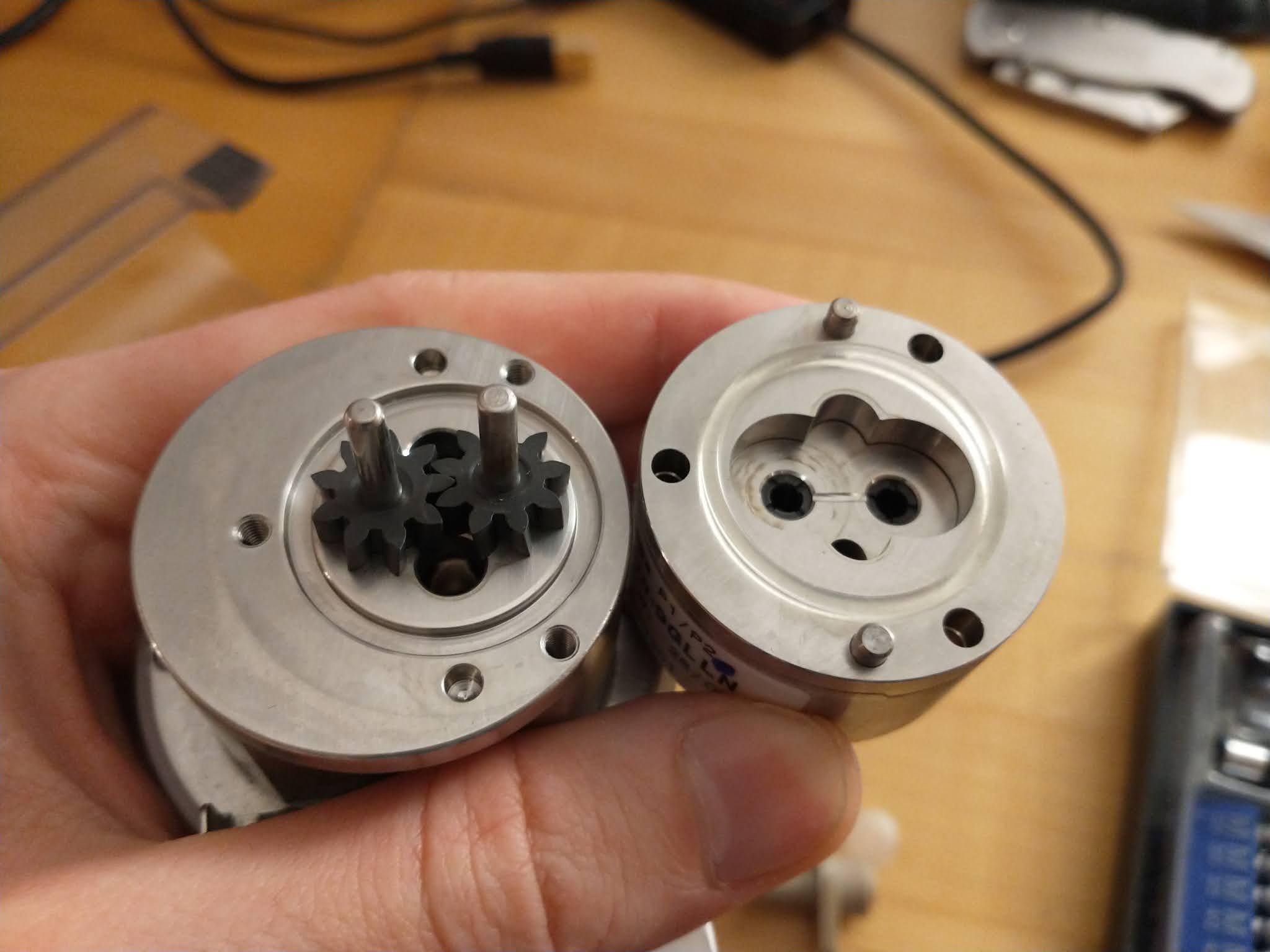
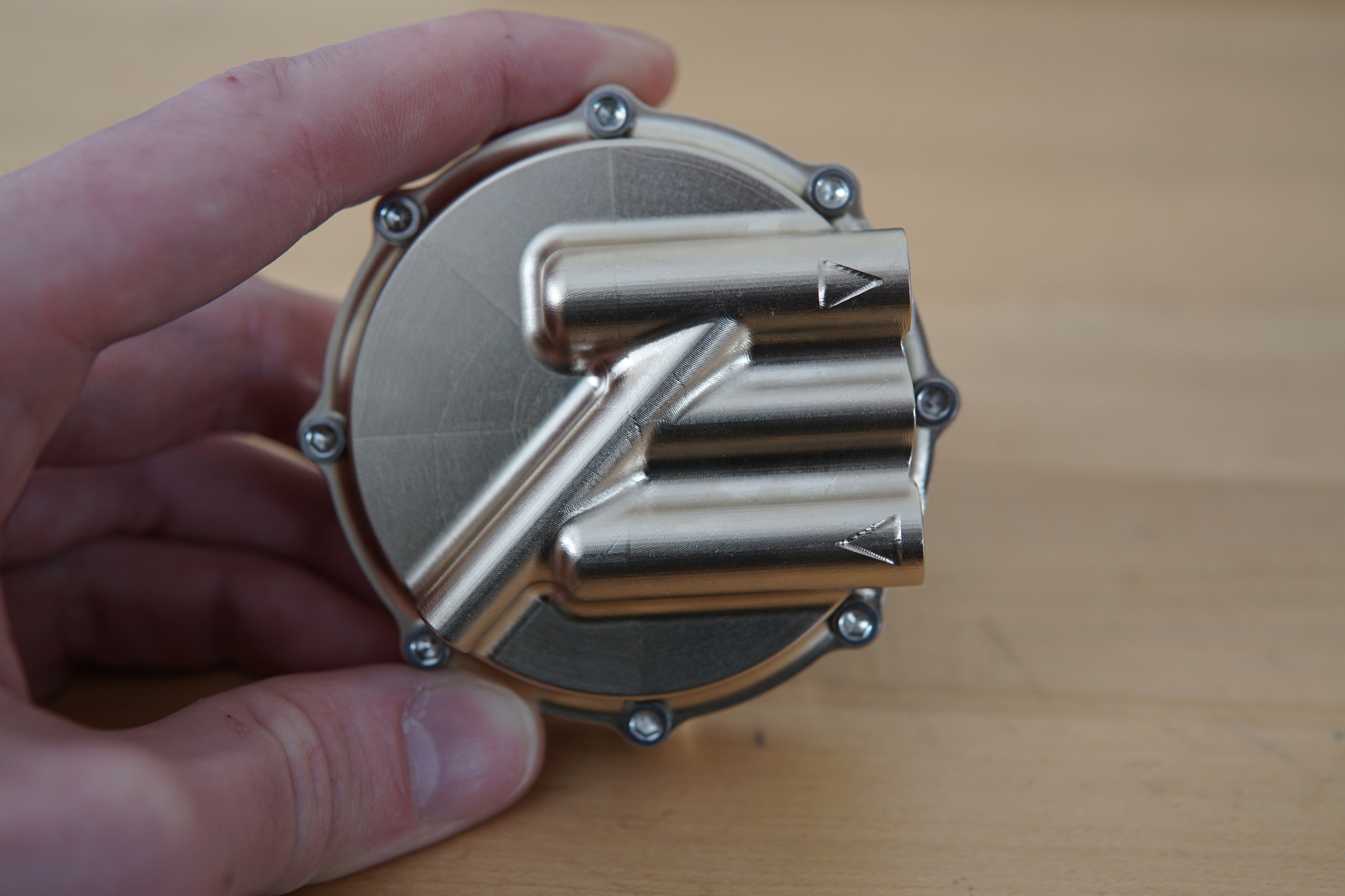
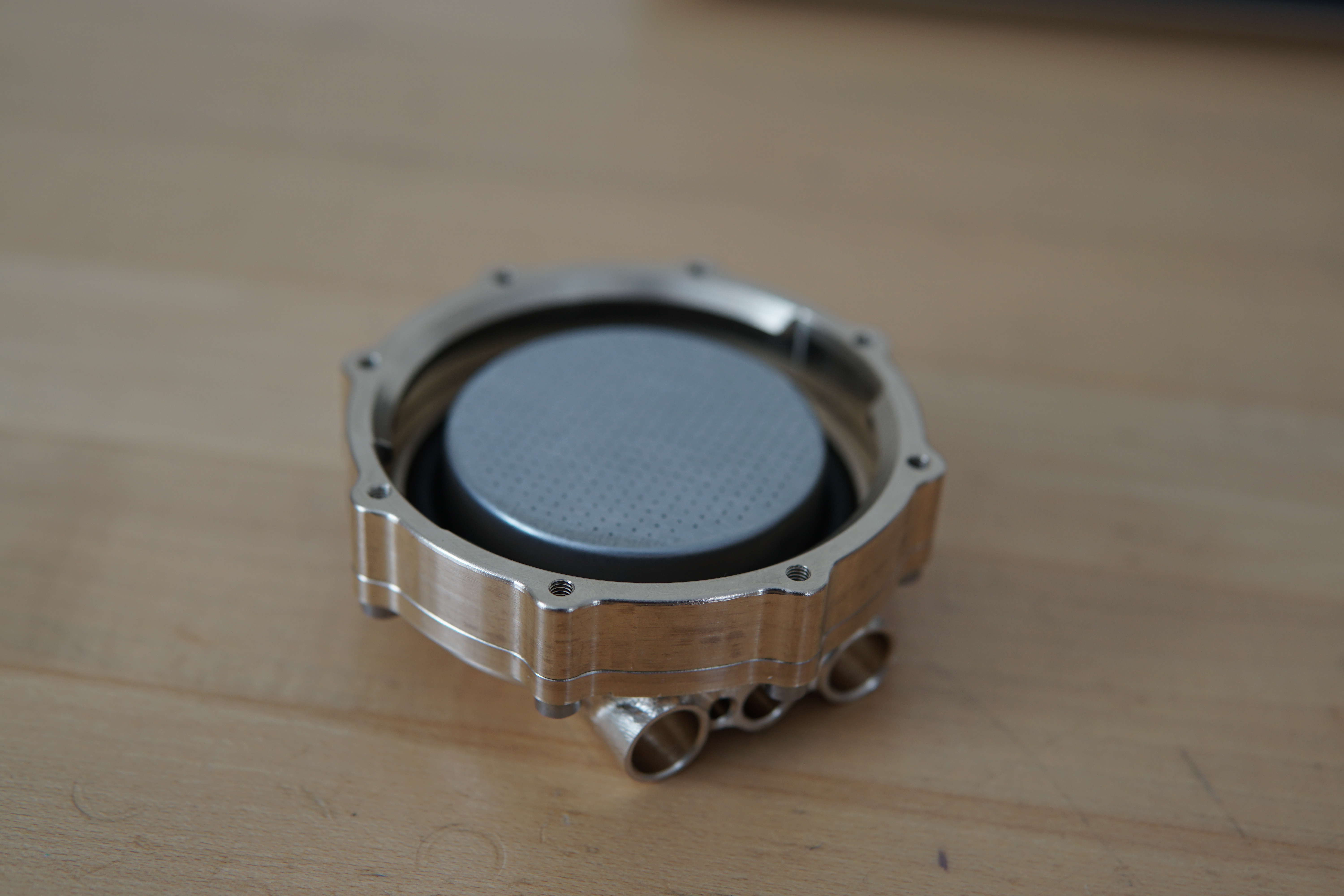
Here's a shot of the inside. The gears and bushings are CF-PEEK and the rest is stainless:
Here's a relevant plot from the datasheet. The blue curve labeled "A" is for a 1 cP viscosity fluid, e.g. water. Should be able to get over 200 psi at greater-than-espresso flow rates. Since the pump displacement is so small, torques needed are in the ~.1 N-m or less range, which means I can use a tiny motor.
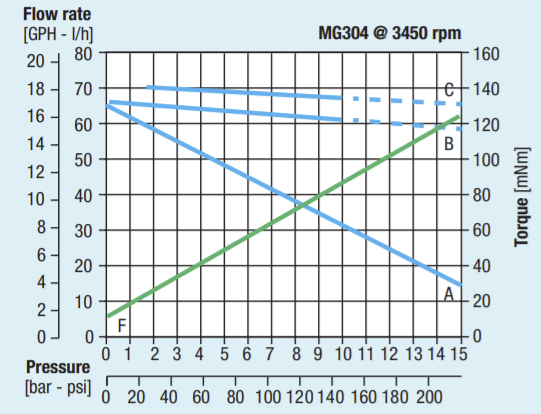
The main downside of gear pumps is leakage - which you can see in the pressure vs flow plot. Gear pumps "seal" by having very close tolerances between the tooth tips and faces of the gears and the pump cavity, so some fluid leaks through these gaps. For this pump it's very linear with pressure - at a constant input speed (which would be a constant flow if there were no leakage), output flow drops off linearly with pressure drop across the pump.
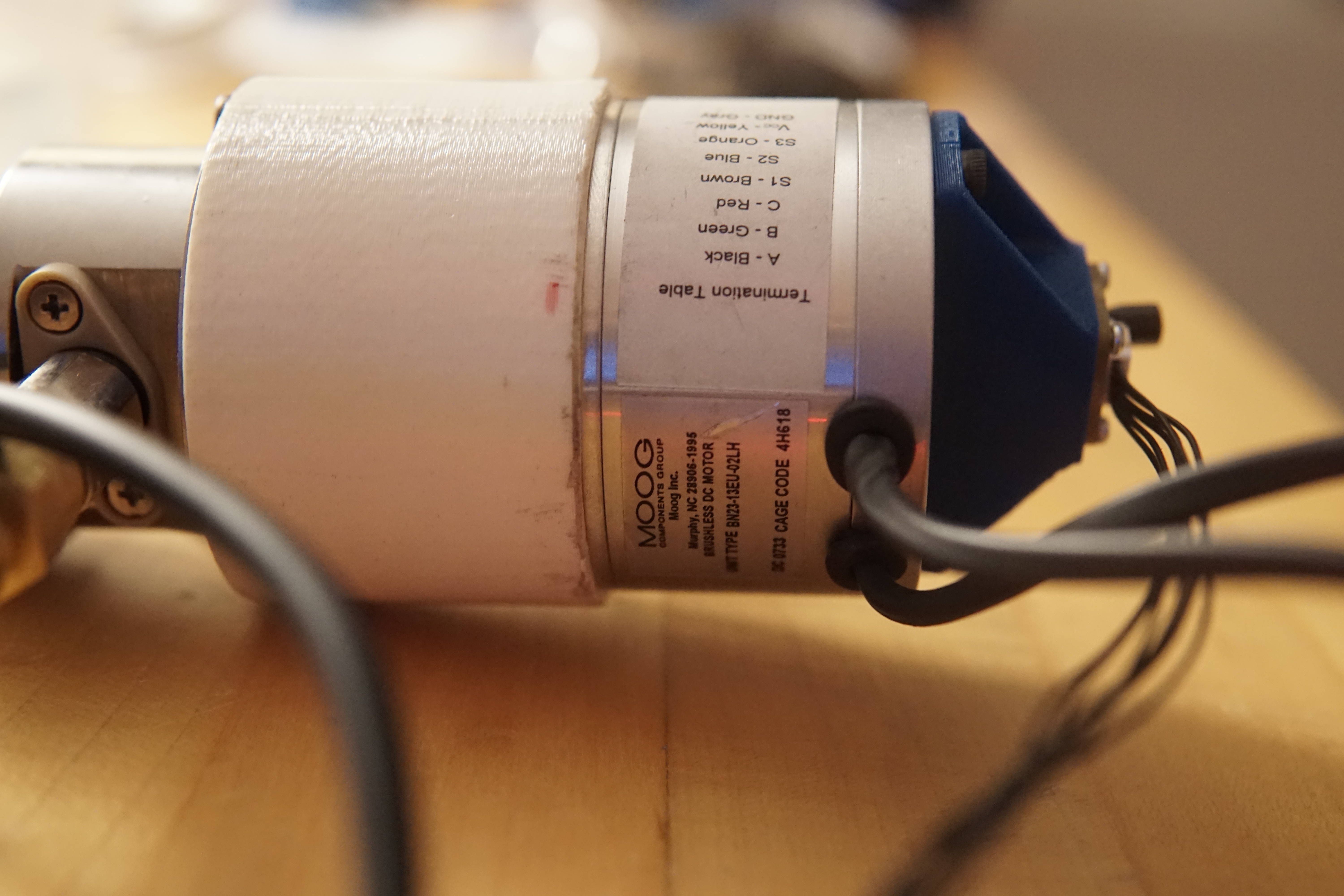
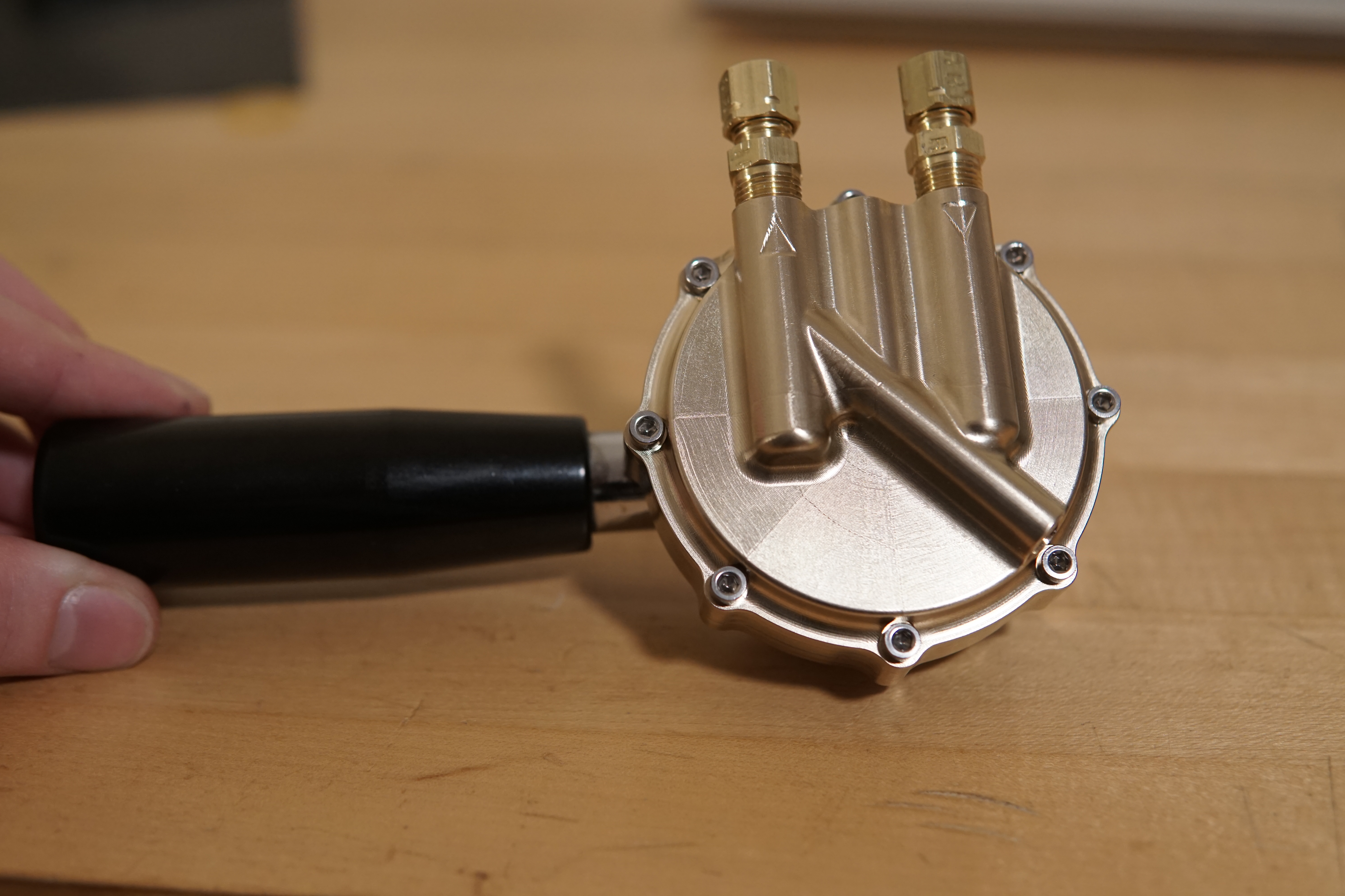
The pump came with a low-end brushed maxon driving it. I swapped that for a Moog BN23 Silencer motor I snagged from a Media Lab trash pile ~7 years ago. One of its larger brethren was used to power the tiny lathe, and another by Dane for Robot Art. A 3d-printed spacer adapts it to the pump. Eventually this'll need to be replaced with a more temperature resistant part, since the water flowing through the pump will get fairly warm.
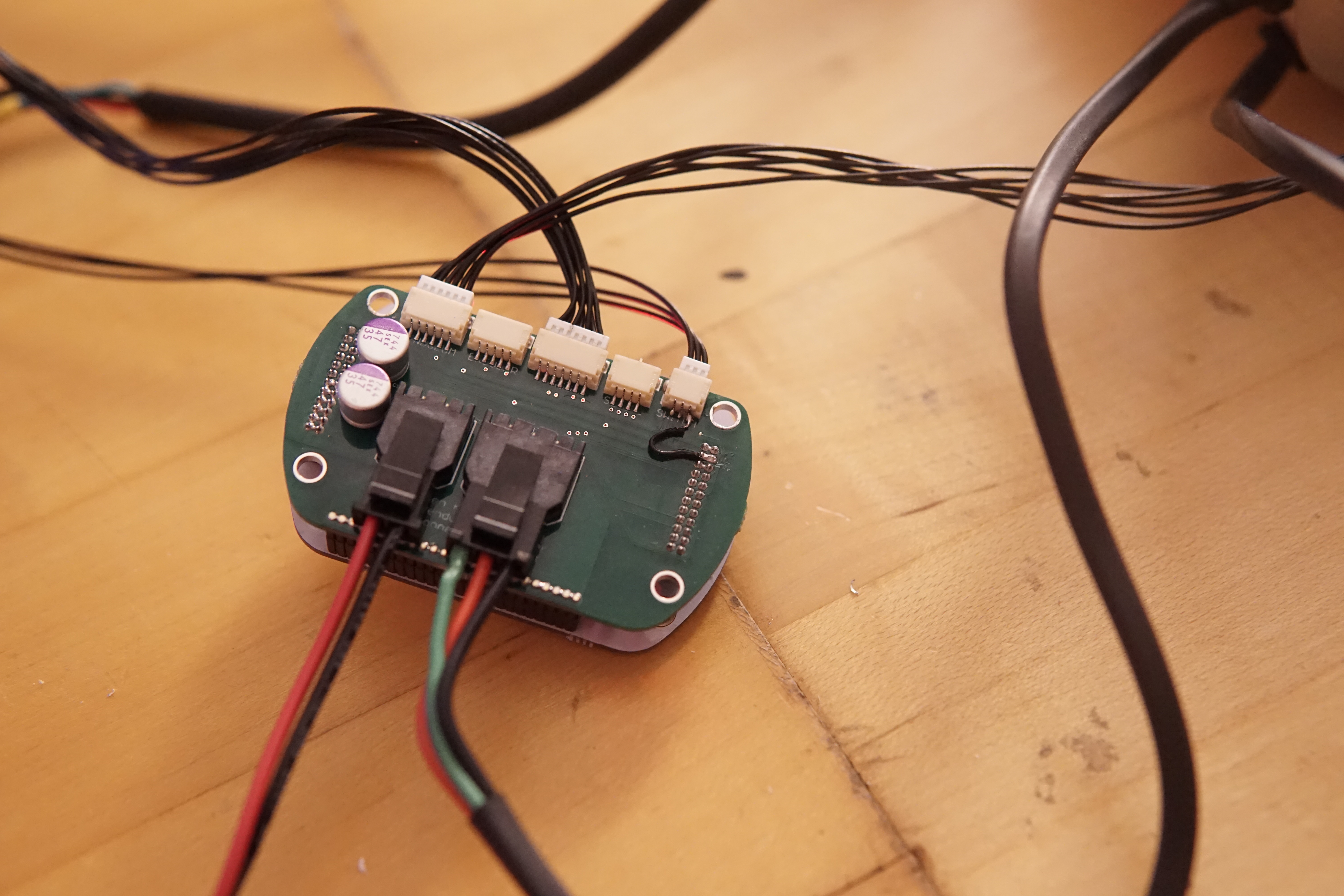
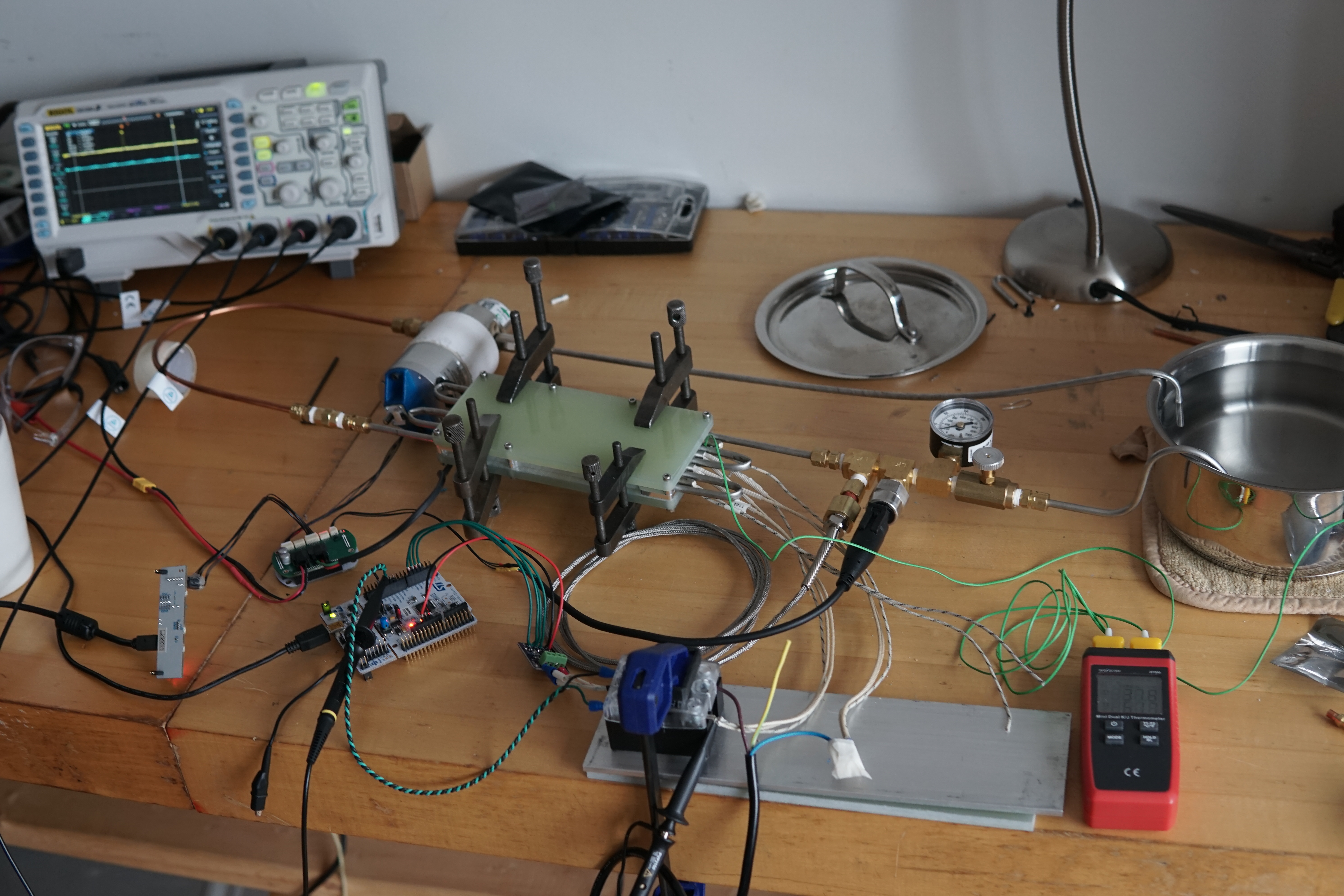
I modified a spare pendulum motor controller so I could plug in the pressure sensor. Eventually I'll have a separate micro for doing all the high-level control and use one of my usual motor drives with the built in encoder, but for now this was the easiest thing to hack together.
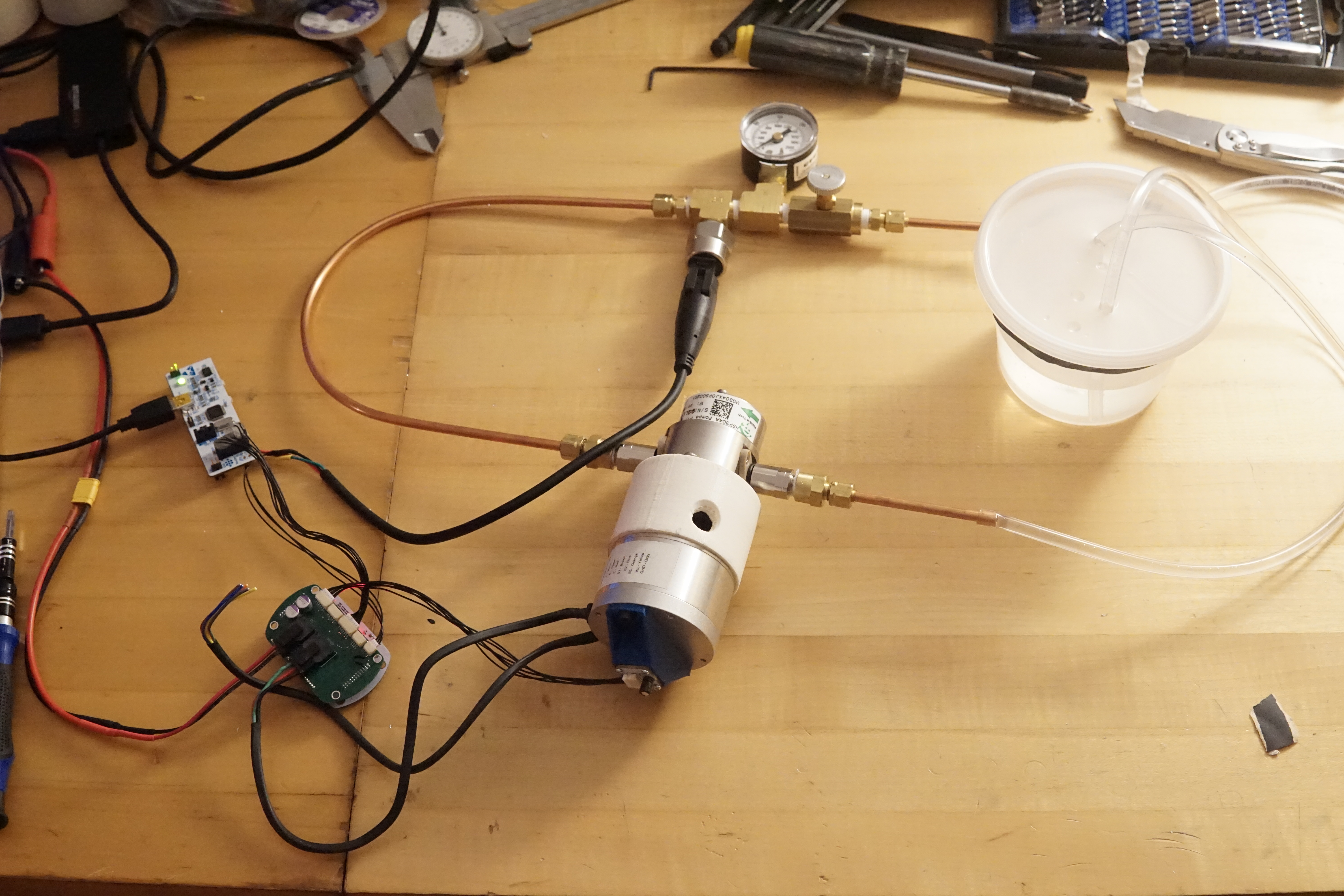
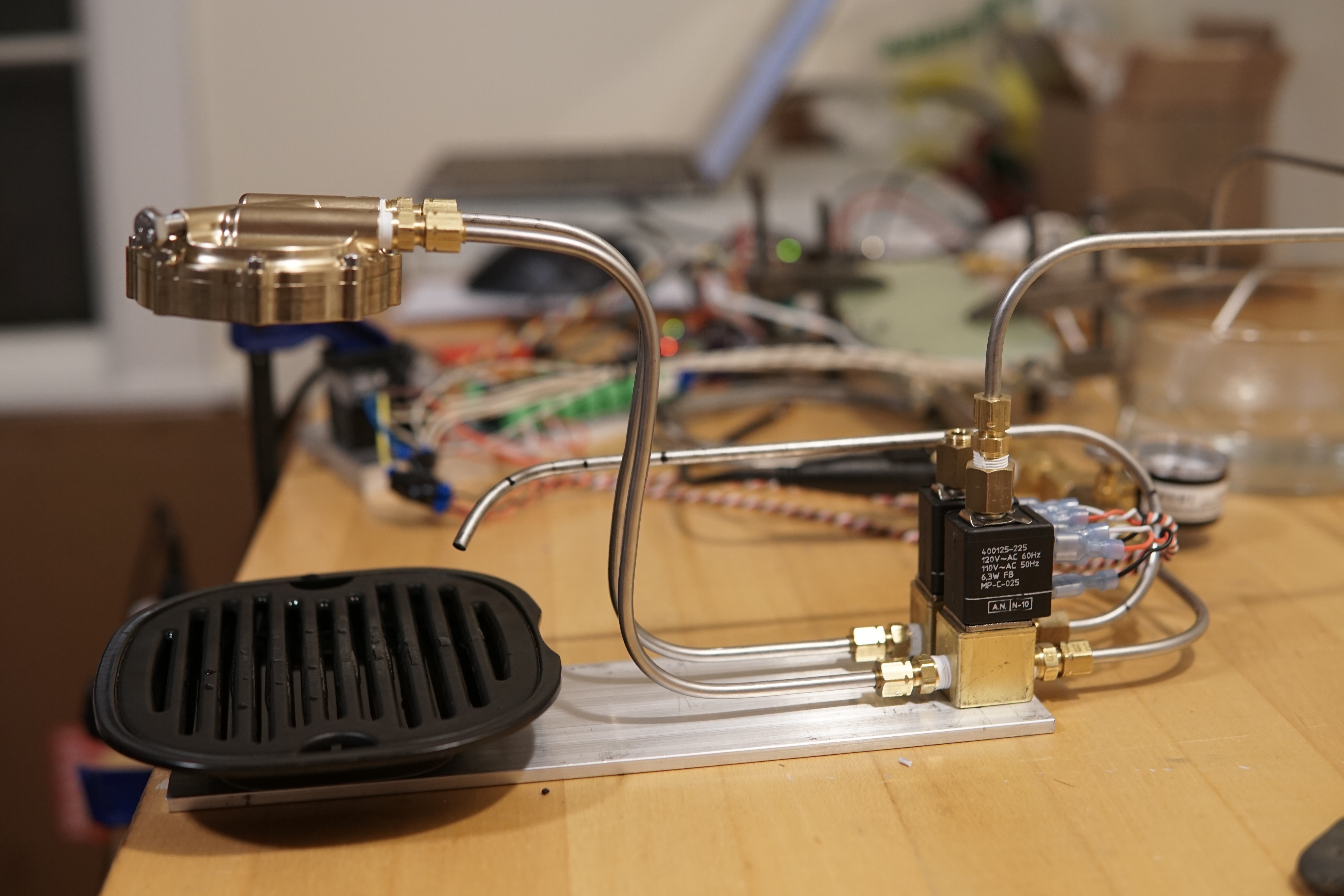
This was my pressure control test bed - the pump and motor, an automotive-style thread-in pressure sensor, a dial pressure gauge, and a needle valve as a variable load;
Testing closed-loop pressure control. The pressure is plotted/setpoint set from the computer, and you can see the response to the needle valve opening and closing. With this setup I can get around 10 Hz of closed-loop pressure bandwidth.
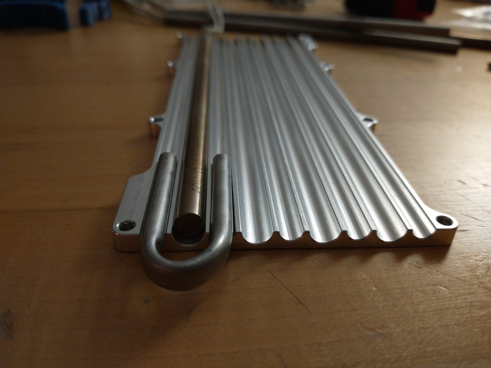
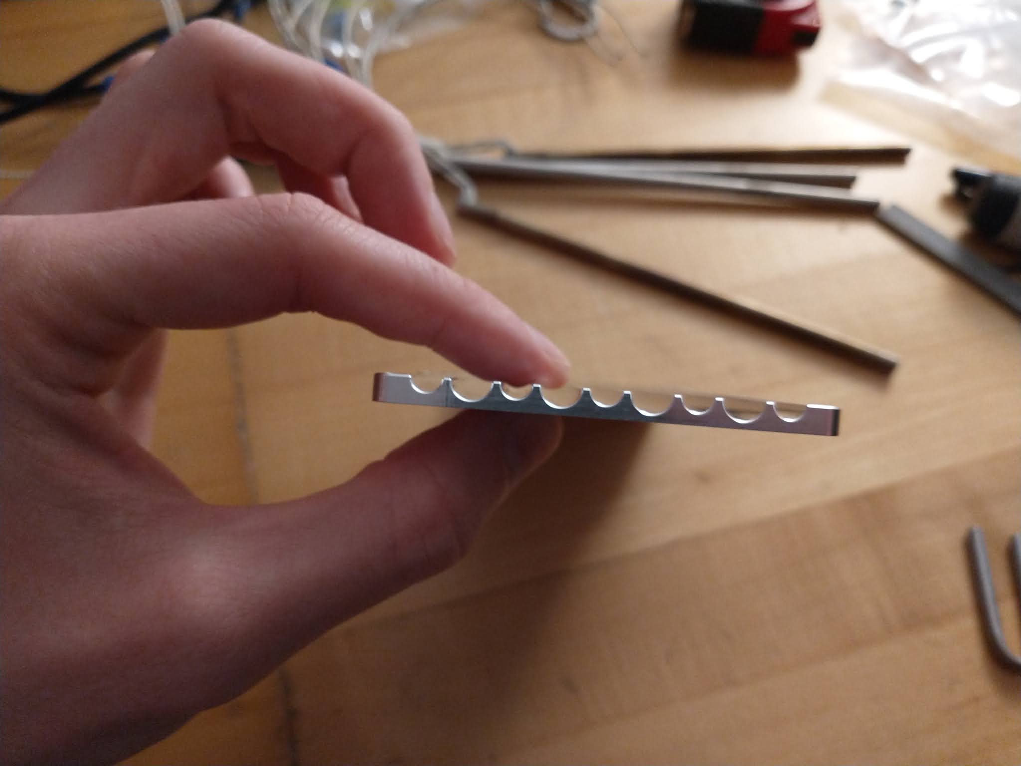

Everything's just bolted to a strip of aluminum right now, and I stole the drip tray from the La Pavoni.
Comments