Varying pitch screw robot build progress
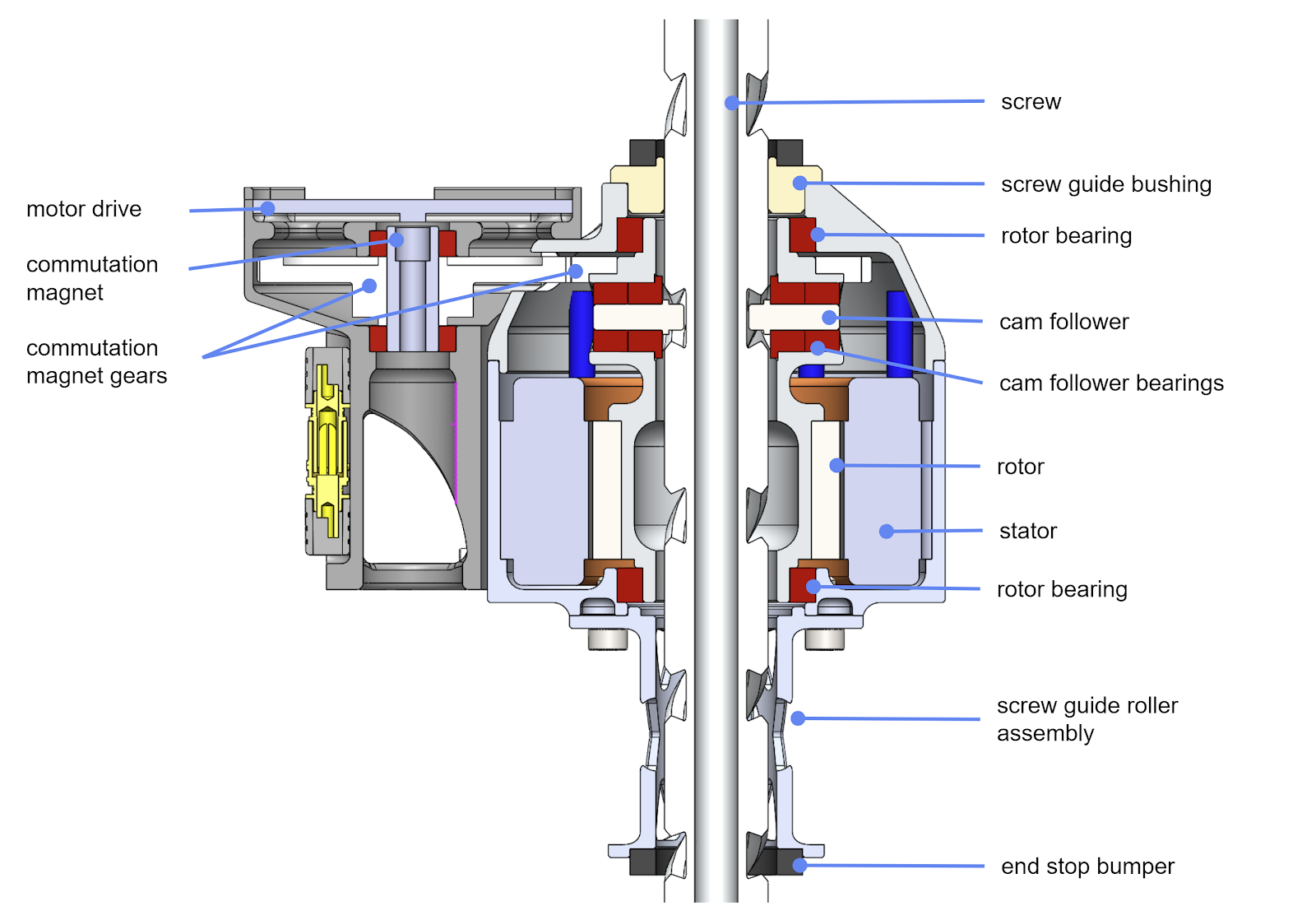
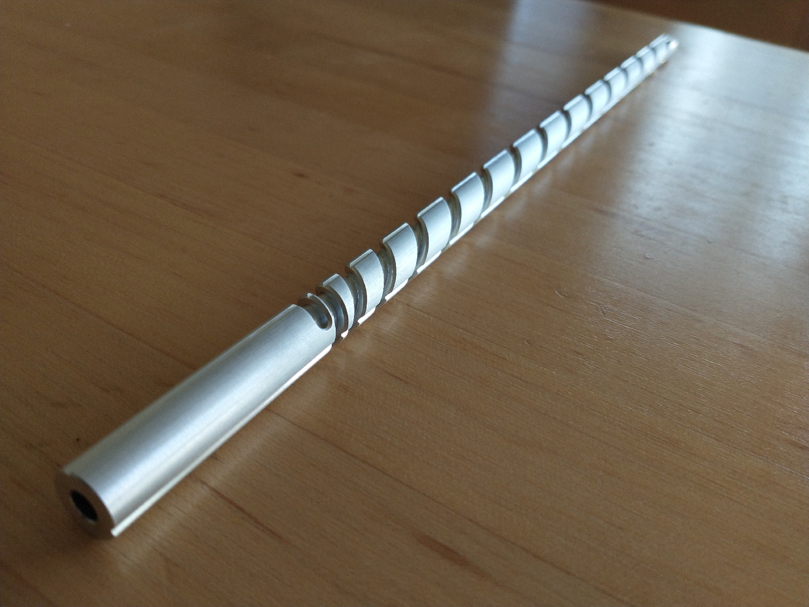
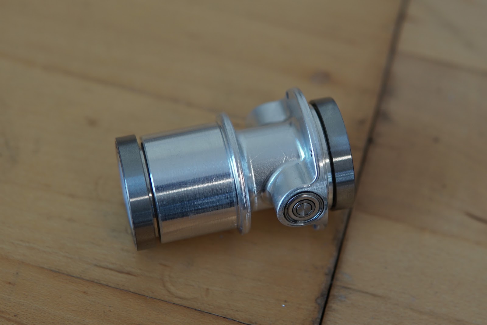
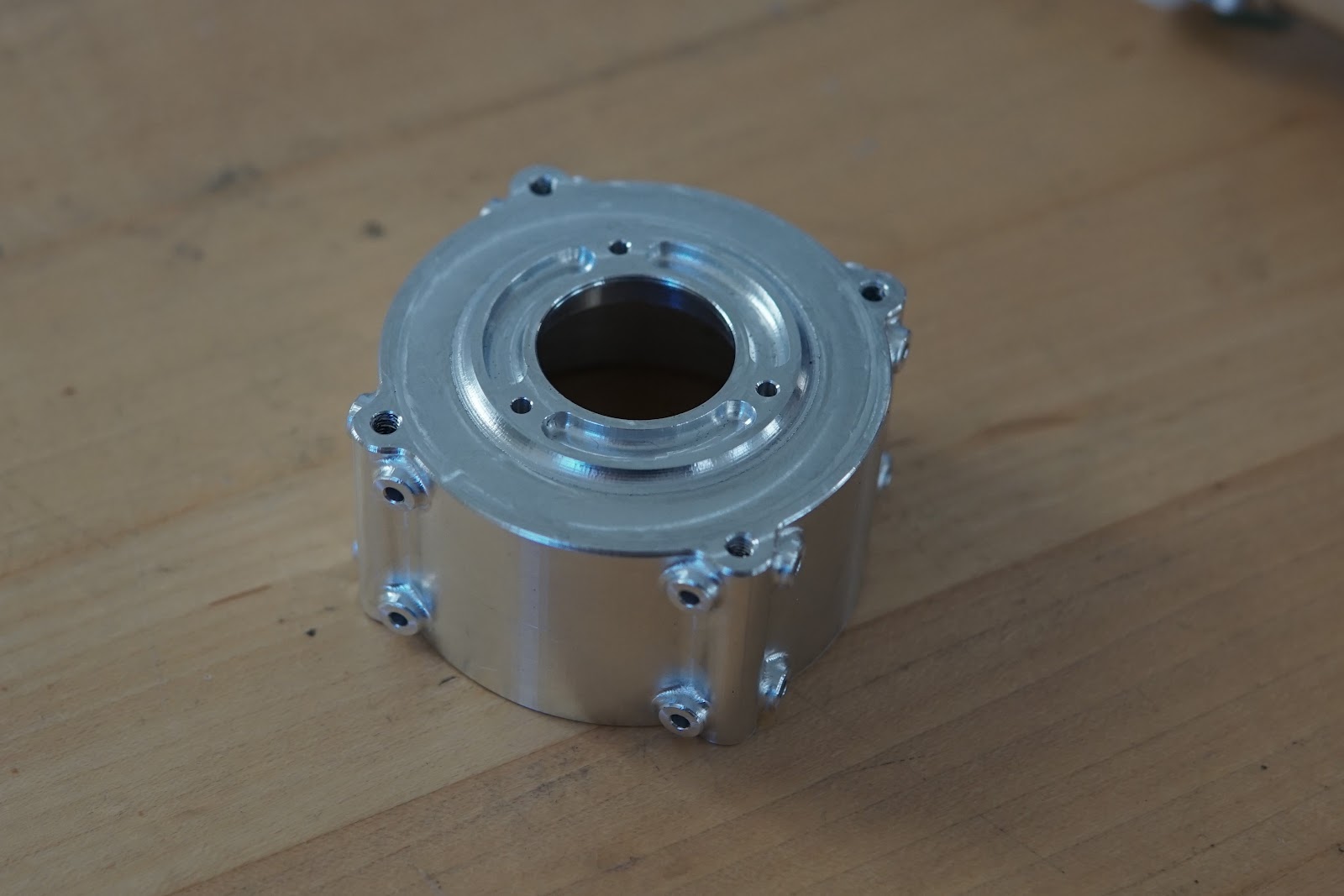
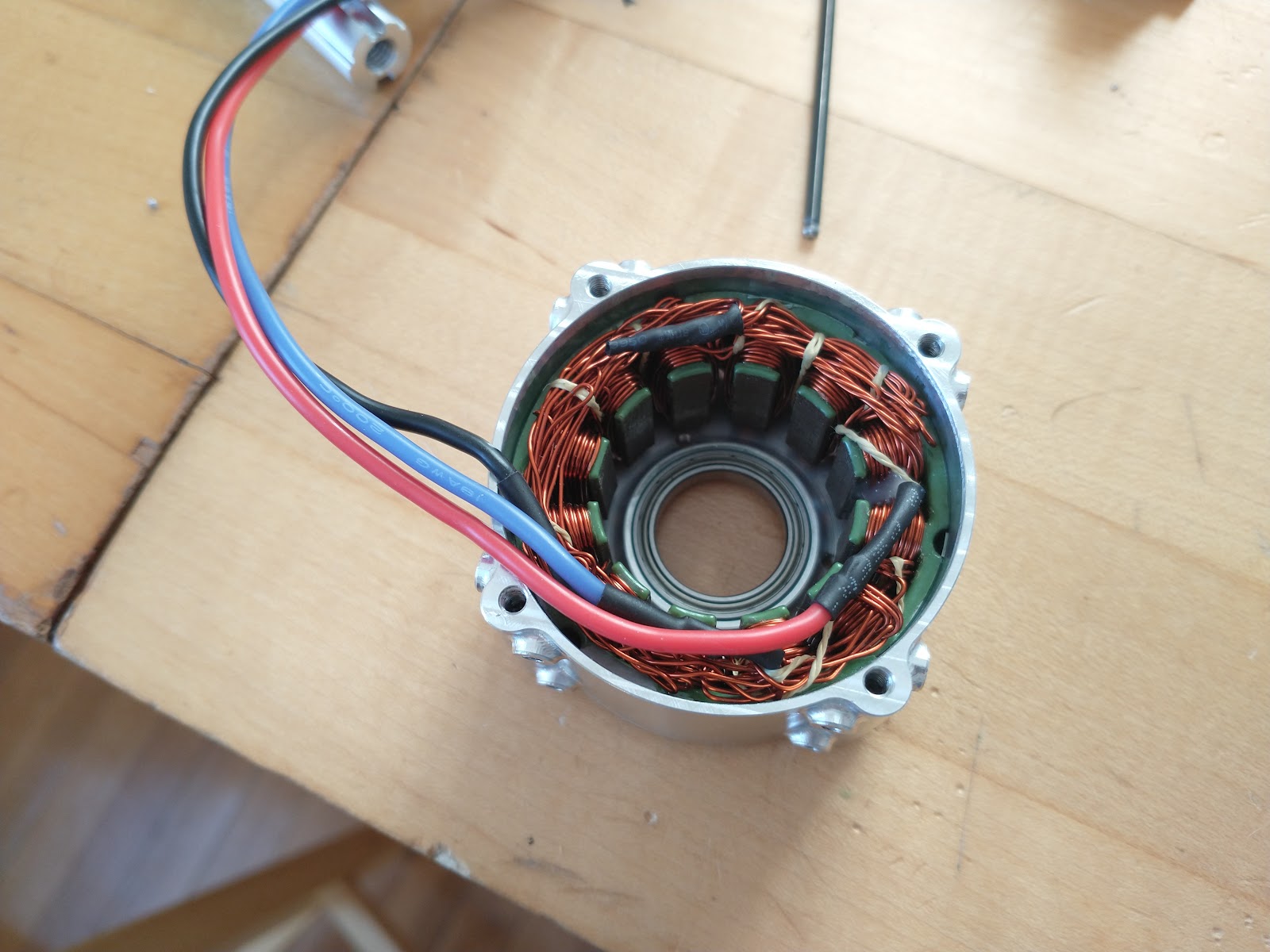
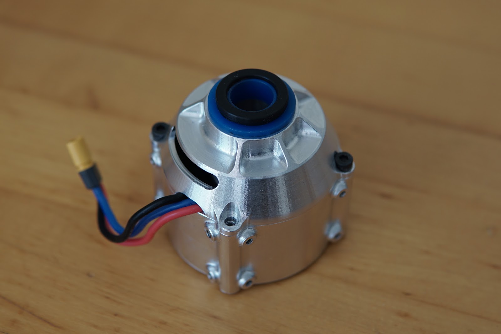
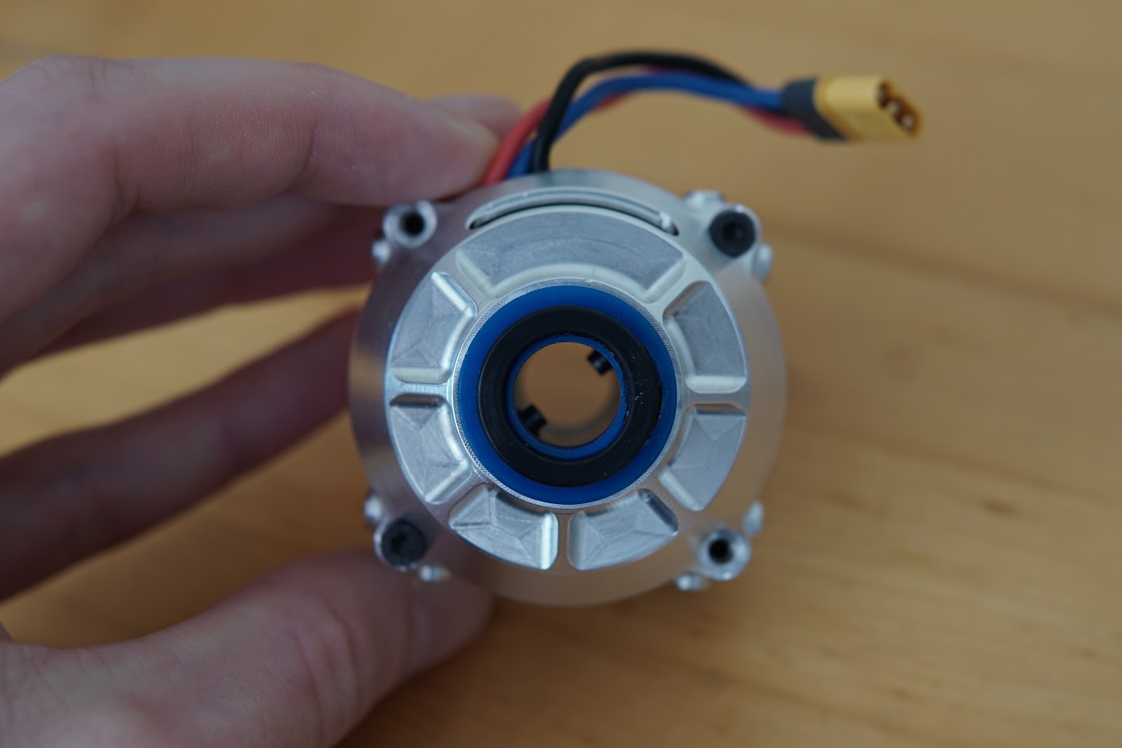
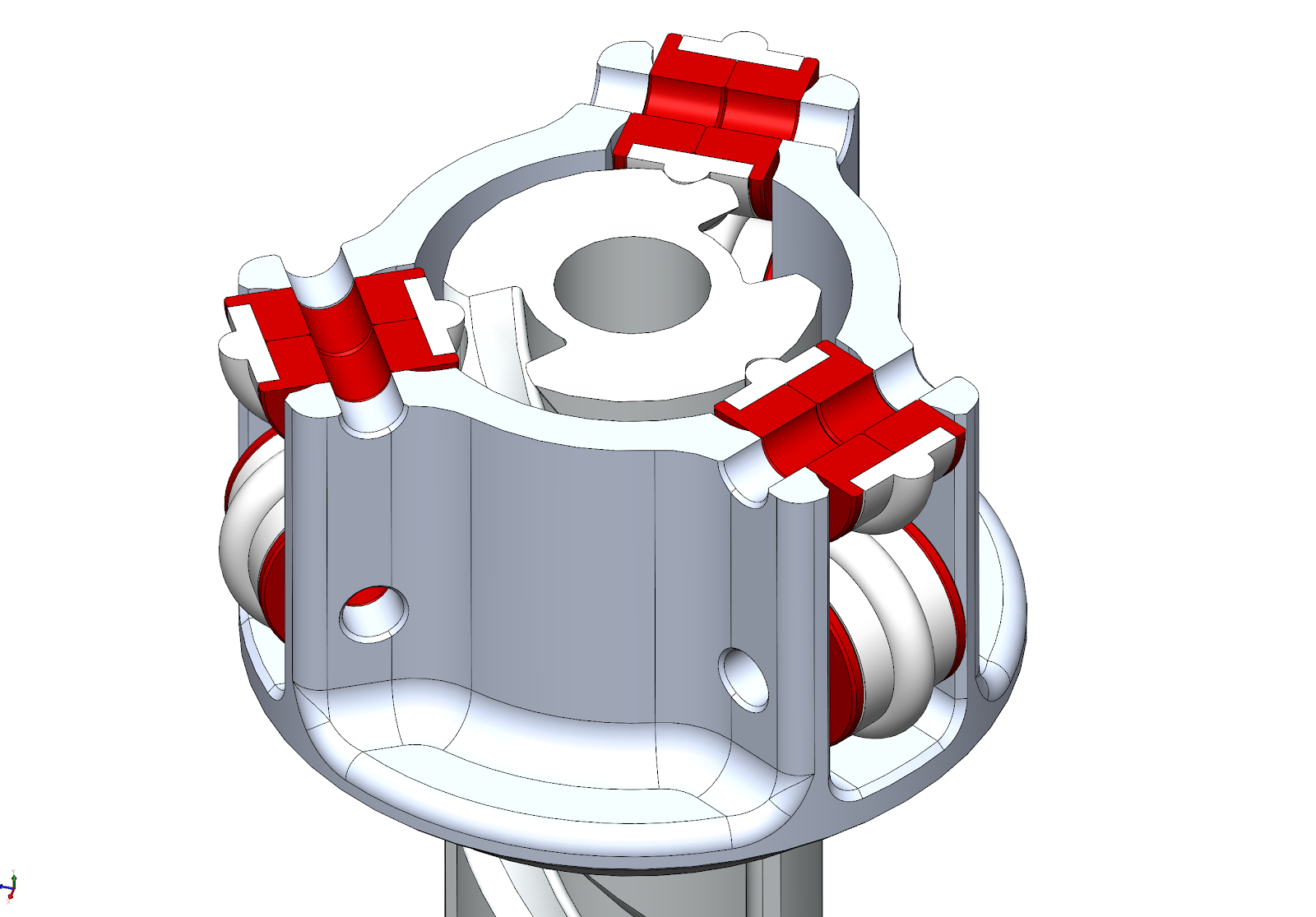
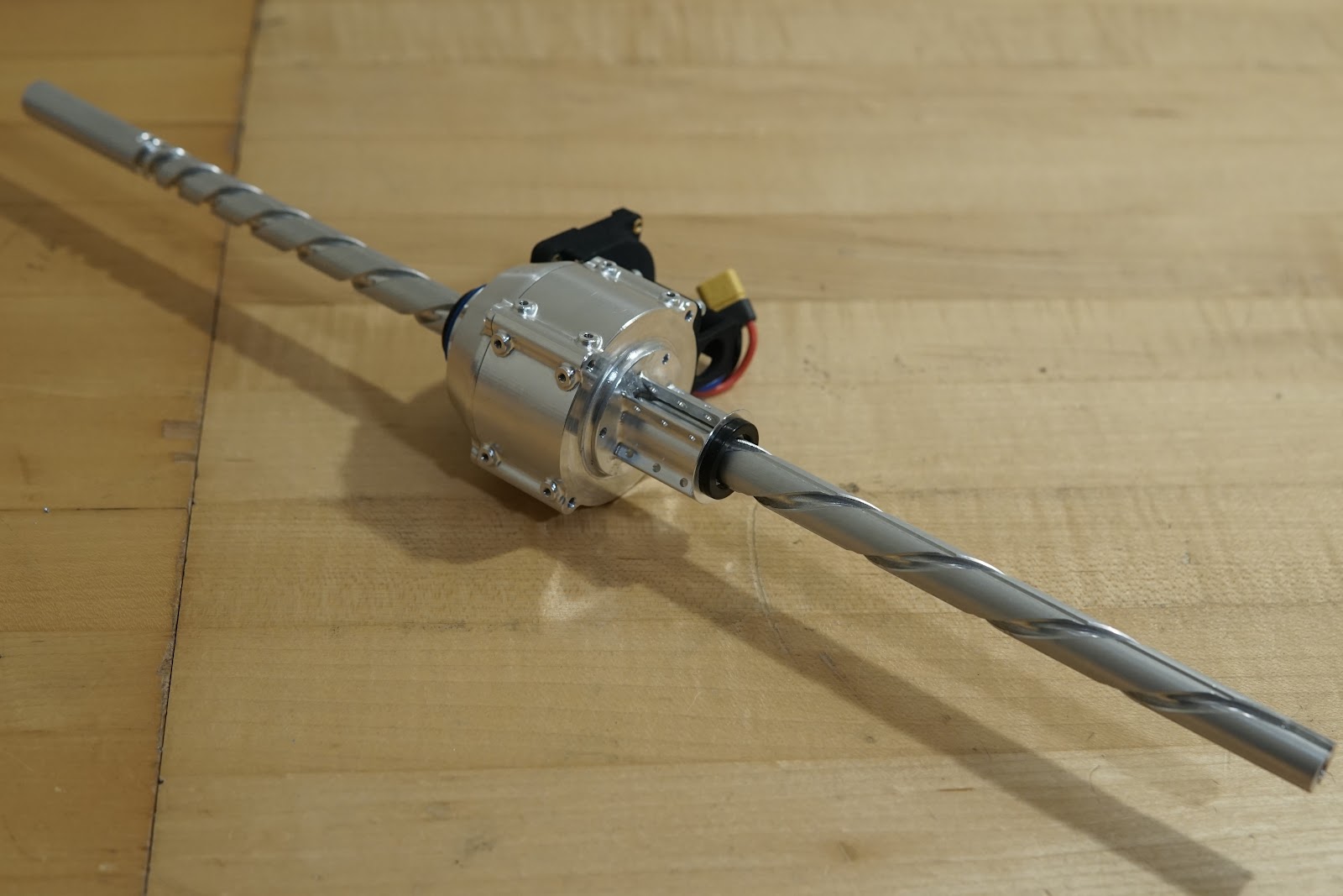
At the center of the mechanism is the varying pitch screw (or barrel cam). The screw passes through a "nut" with two cam followers, which drives the screw axially as it turns. The nut directly supports the rotor of an electric motor (specifically a T-motor RI50). The screw passes through the center of the motor's stator, and is constrained by a guide bushing at the top, and 3 sets of guide rollers at the bottom, which roll in axial grooves on the screw and react the motor torque.
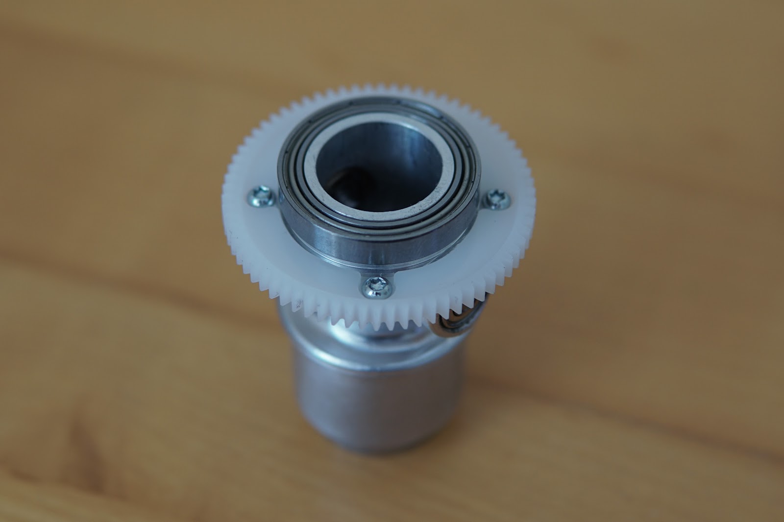
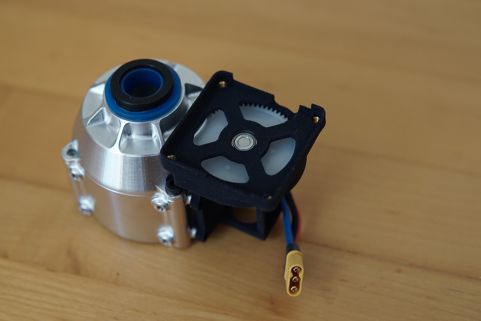
One kind of sketchy bit is that I'm measuring the rotor position through a 1:1 spur gear pair. Ideally I would have used an off-axis encoder with a through bore to pass the screw. I didn't do that though - I already have a few dozen of my mini cheetah motor drives on hand, and I actually couldn't find any appropriately sized thru-bore absolute encoders that were good for ~12k RPM. I maybe could have used the iC Haus IC-MU (actually, one of the last things I did at the lab was make a version of my drive with that encoder IC, so most of the work is done already), but with the magnet target I need to clear the screw it's rated at exactly 12k RPM, which seemed like cutting it close. Maybe eventually I'll do a purpose-built version of the motor drive for this, if the geared encoder turns out to be problematic. Still, offsetting the encoder seemed like a better idea than offsetting the whole motor and having a belt or gears to transmit torque to the cam followers - this way the gears don't take any torque and can be plastic and very thin.
On to actually building the thing:
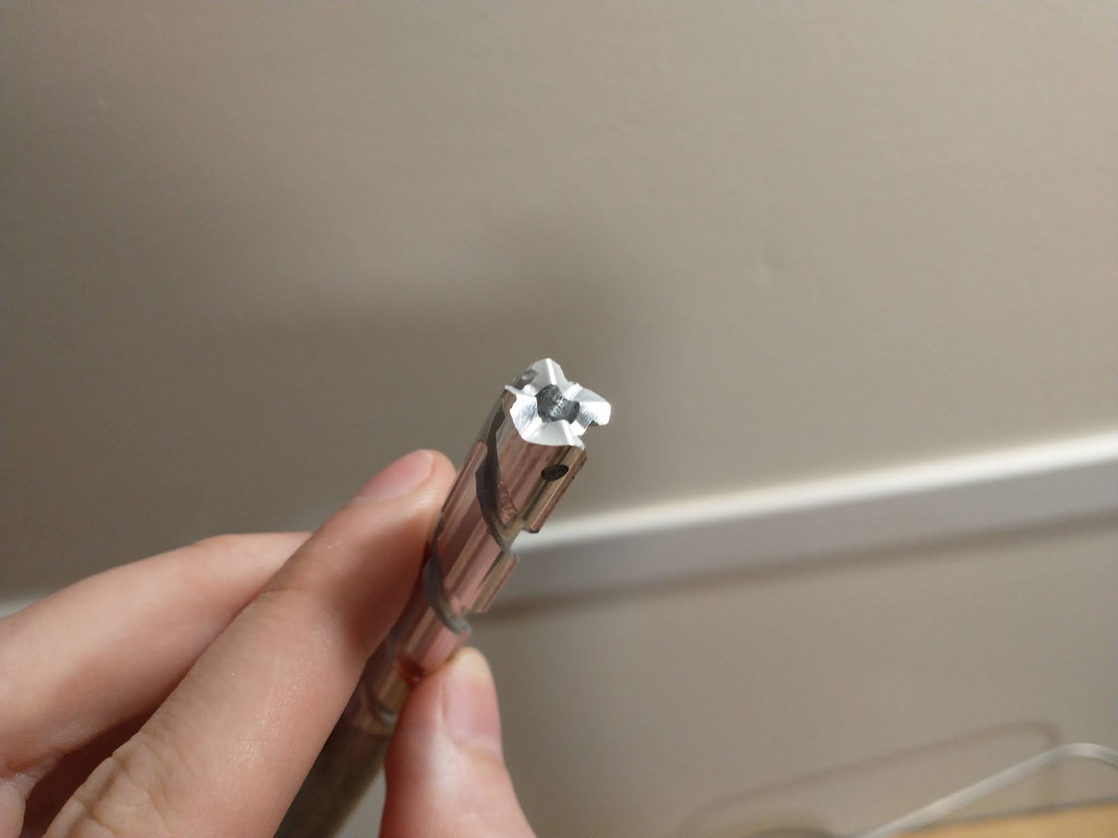
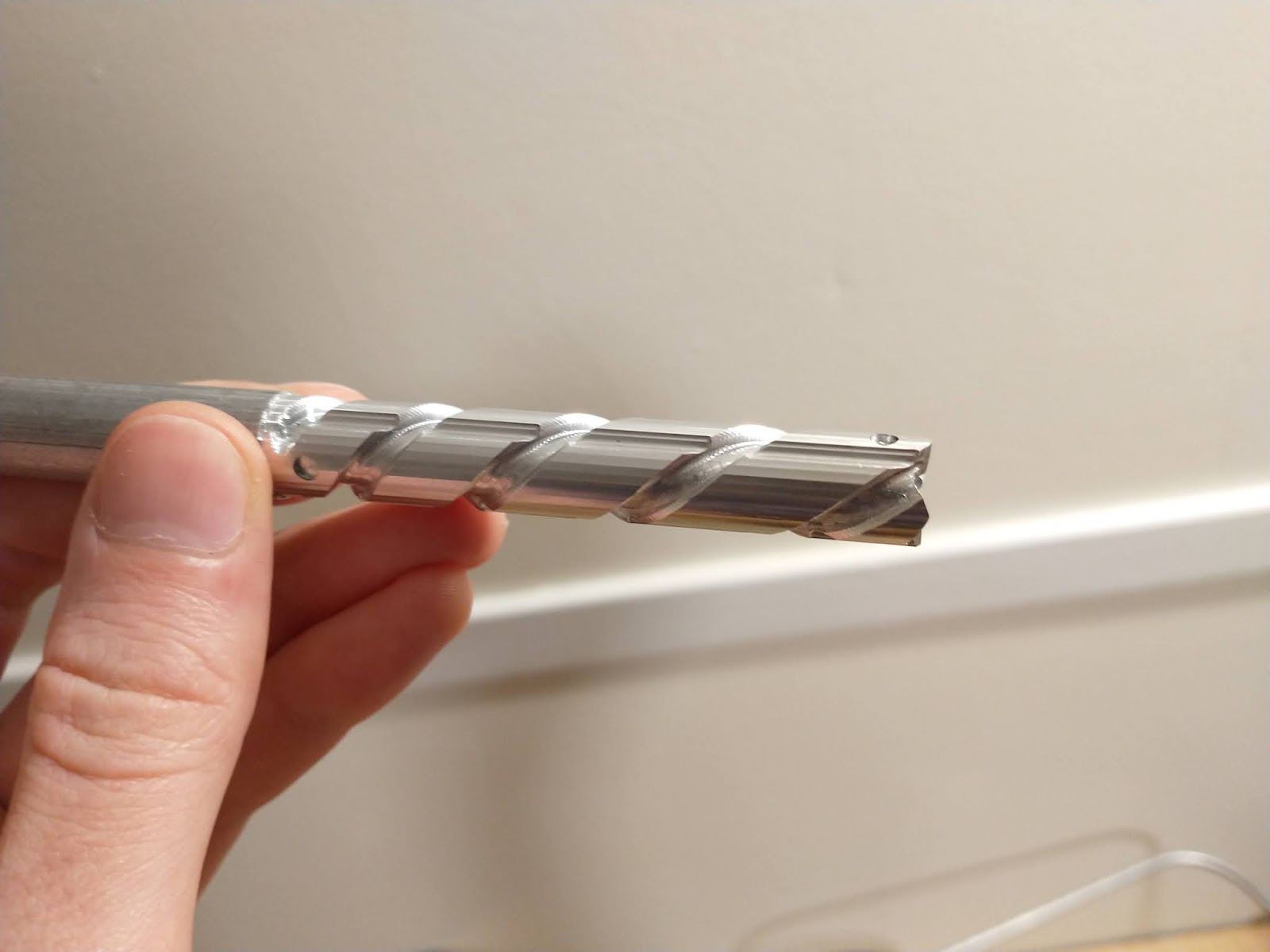
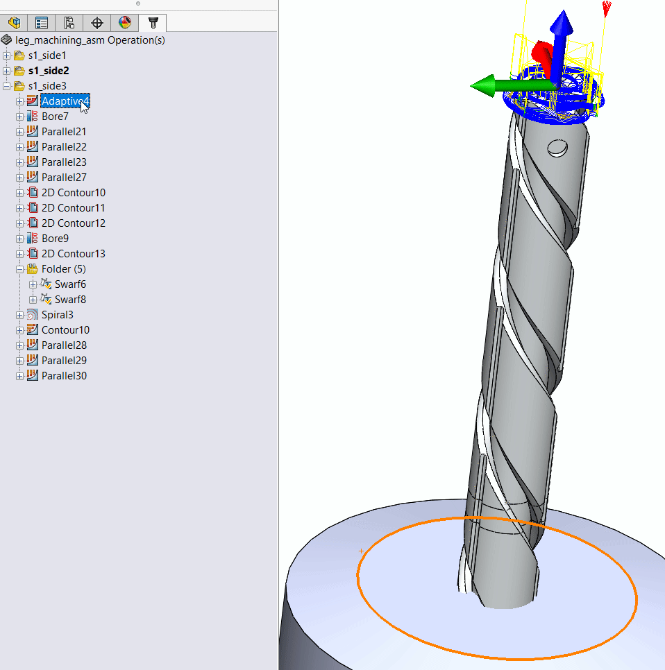
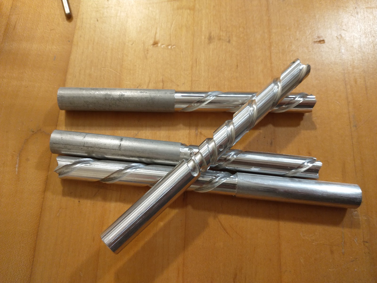
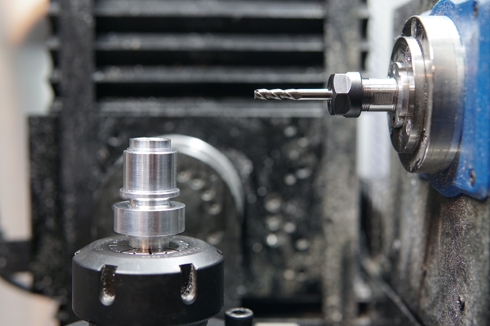
Machining the screw was quite a saga, and I actually ended up outsourcing the part. I could have eventually finished it with the approach I was taking, but it ended up not being worth it for now. It's the wrong shape for the 5-axis mill, so machining the full part required it to be broken into 3 separate pieces with two setups per piece, with extremely good alignment between operations required for smooth cam surfaces. I did think about building some sort of dedicated rotary-CNC contraption, or rigging some mechanism to one of the local bridgeports with an encoder and motor driven rotary axis - maybe if I want to be able to rapidly revise this part I'll revisit one of those ideas.
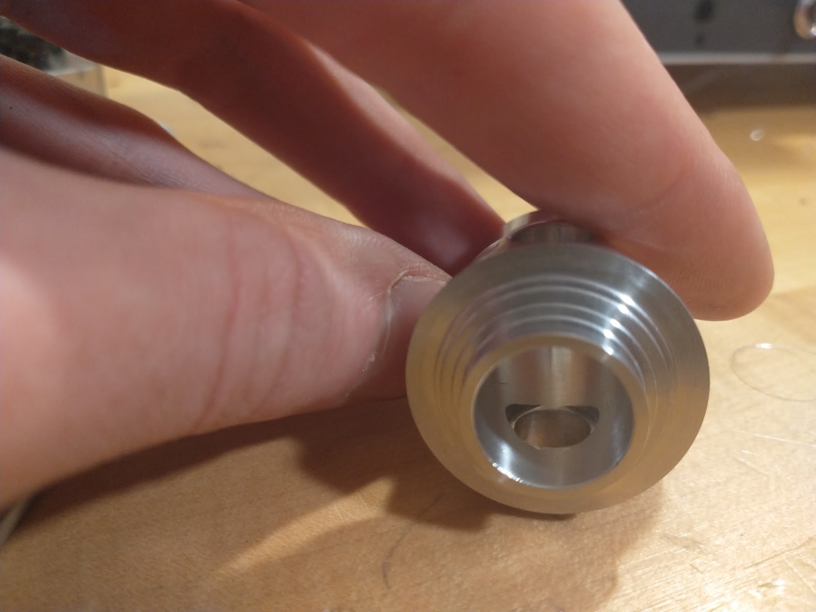
Here's an example of one operation done on one of the parts. For locating adjacent pieces and transferring torque, I put a hirth-esque coupling at the ends. The plan was to drill all the way through the center of each part and clamp the whole thing together with a long tie rod down the center.
These can just barely be inserted from the inside through the central bore in the rotor. I'd probably change up this arrangement a little if I had to remake the rotor as it was pretty tricky to assemble, but this design did minimize the cantilever of the cam followers, and very solidly supports the thrust loads on the cam followers (due to both cam scrubbing and centripetal acceleration from the rotor spinning)
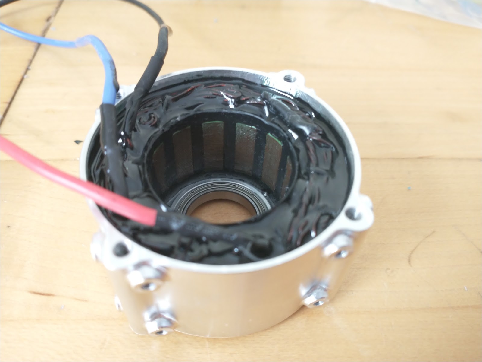
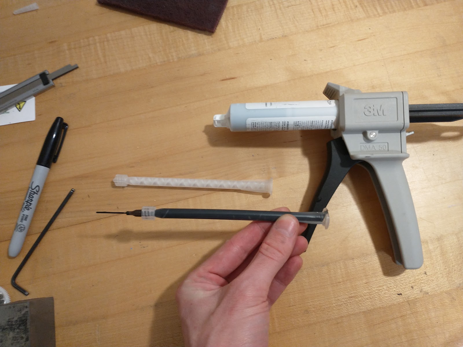
Here it is after filling with epoxy, while the mold is still in place:
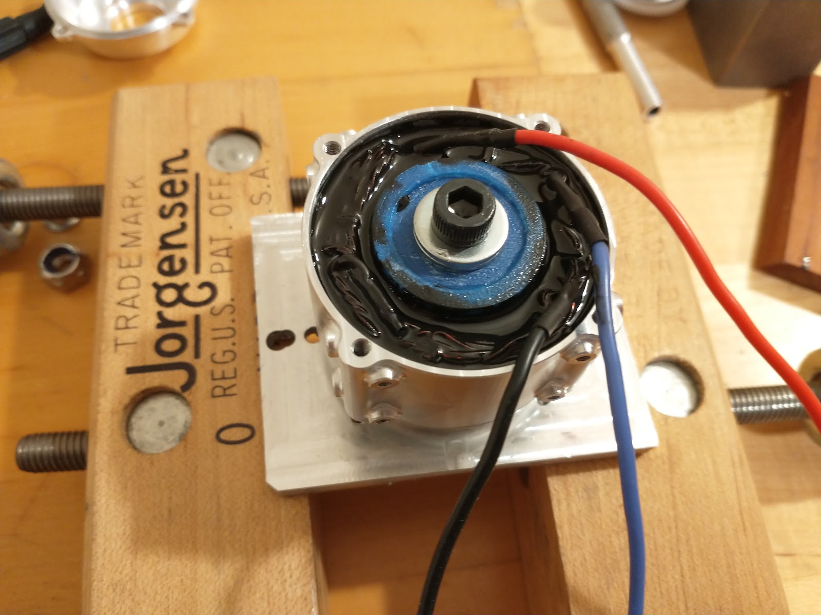
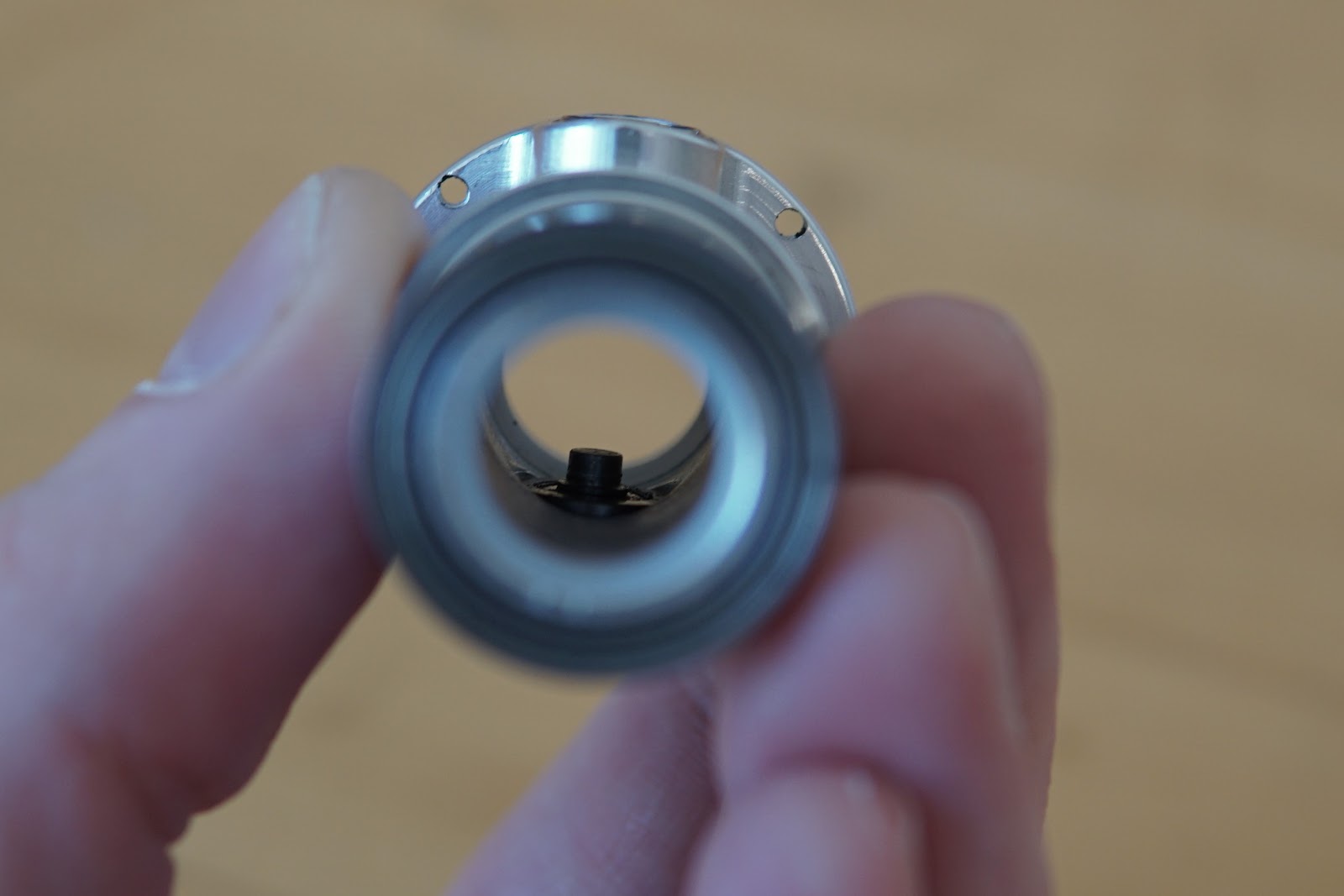
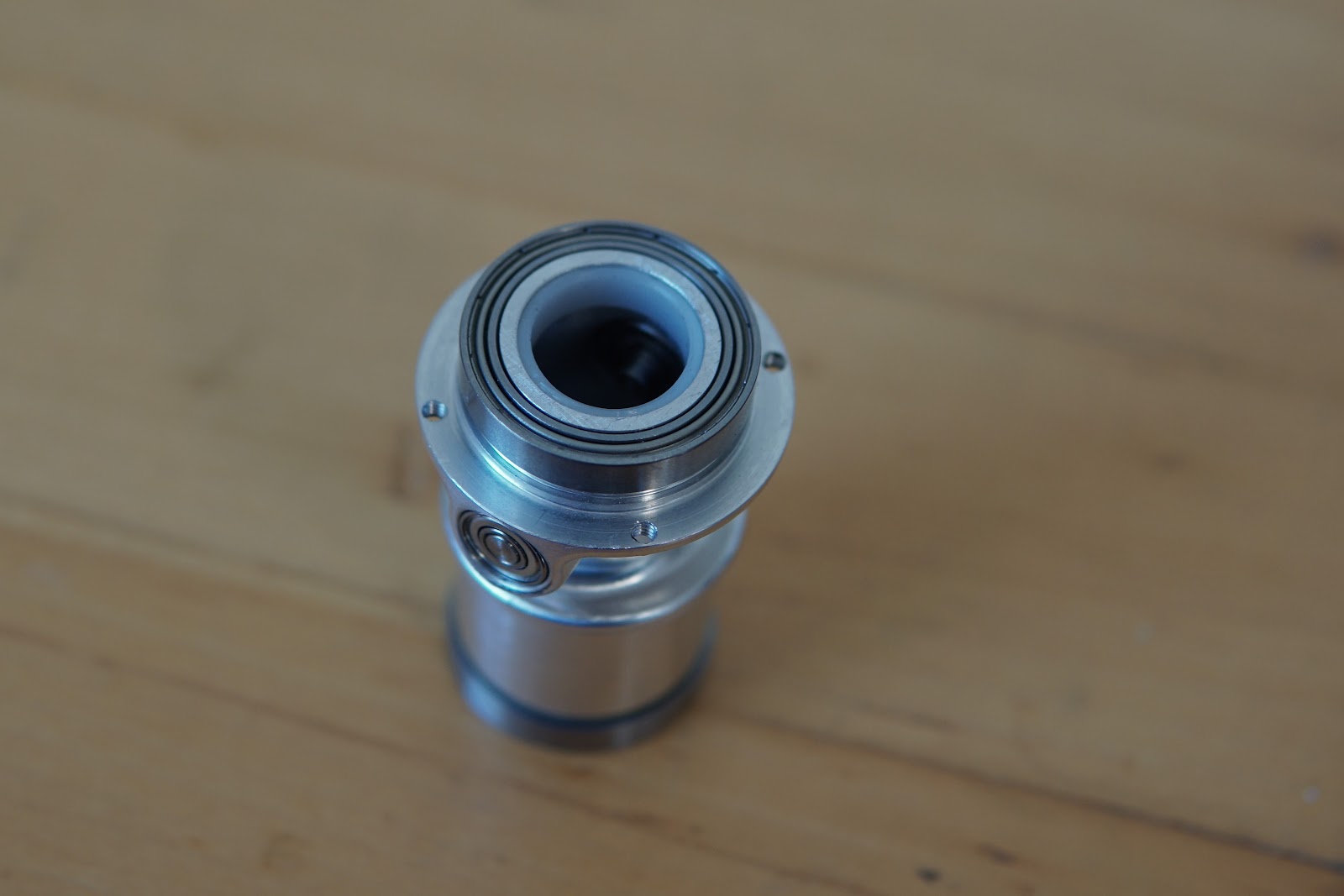
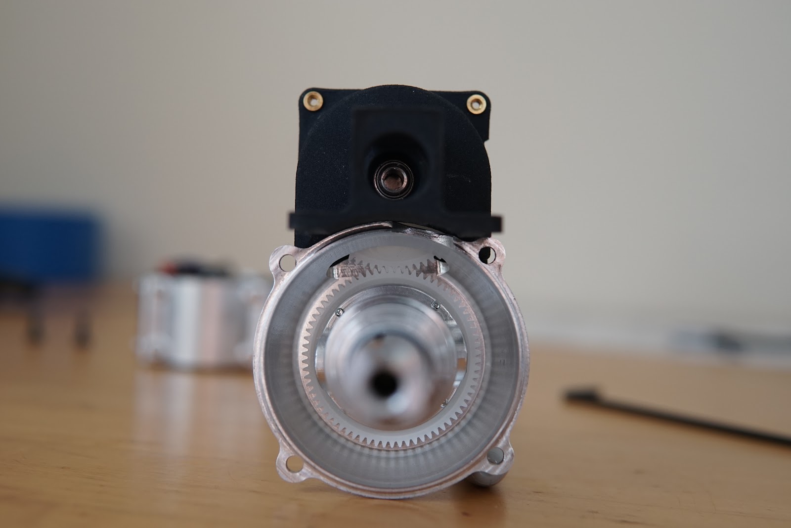
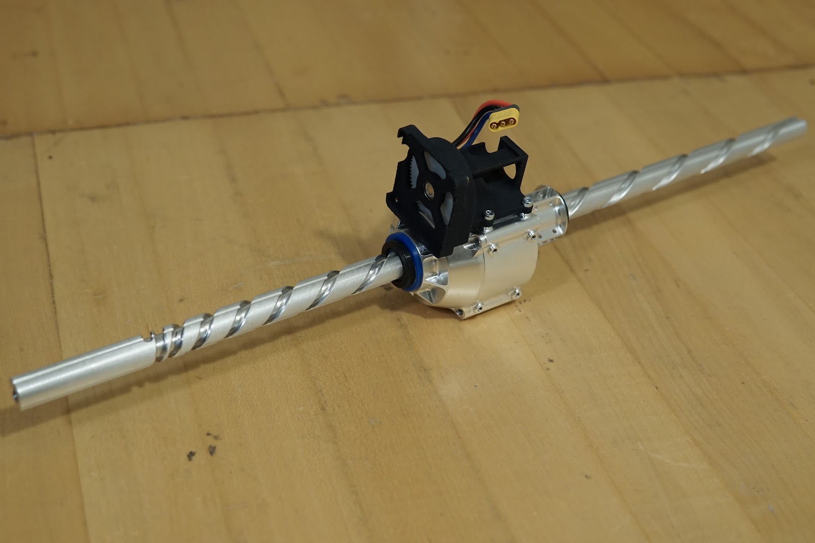
Here's the motor drive mount attached. The motor drive mount is an HP MJF 3d-printed part. At the center is a pair of bearings fan aluminum shaft with a tiny diametric magnet pressed into the end, for sensing the rotor position. The spur gear in the motor drive mount meshes with the spur gear on the rotor, as seen two pictures down.
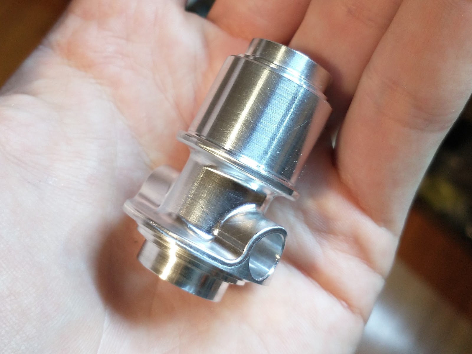
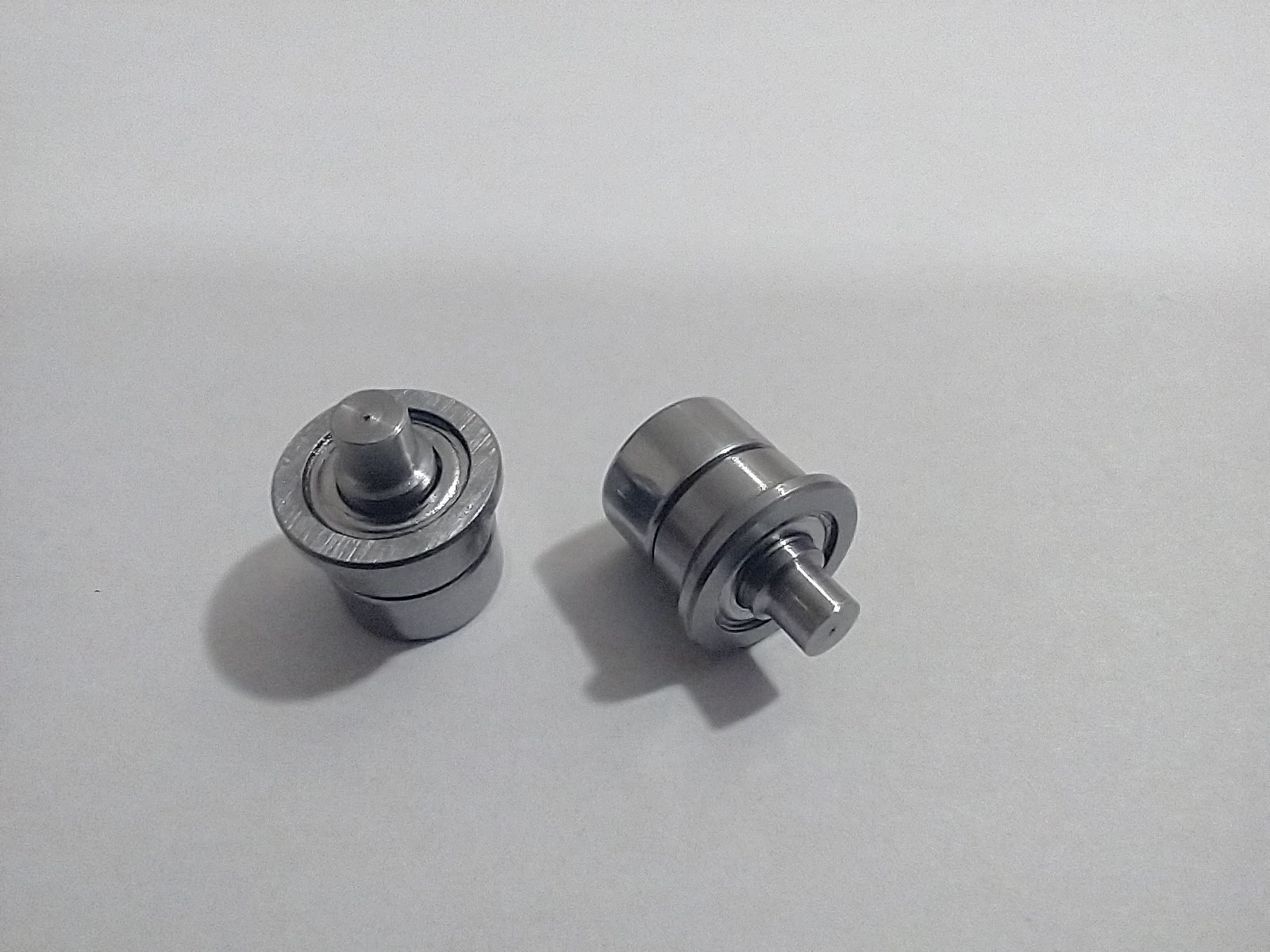
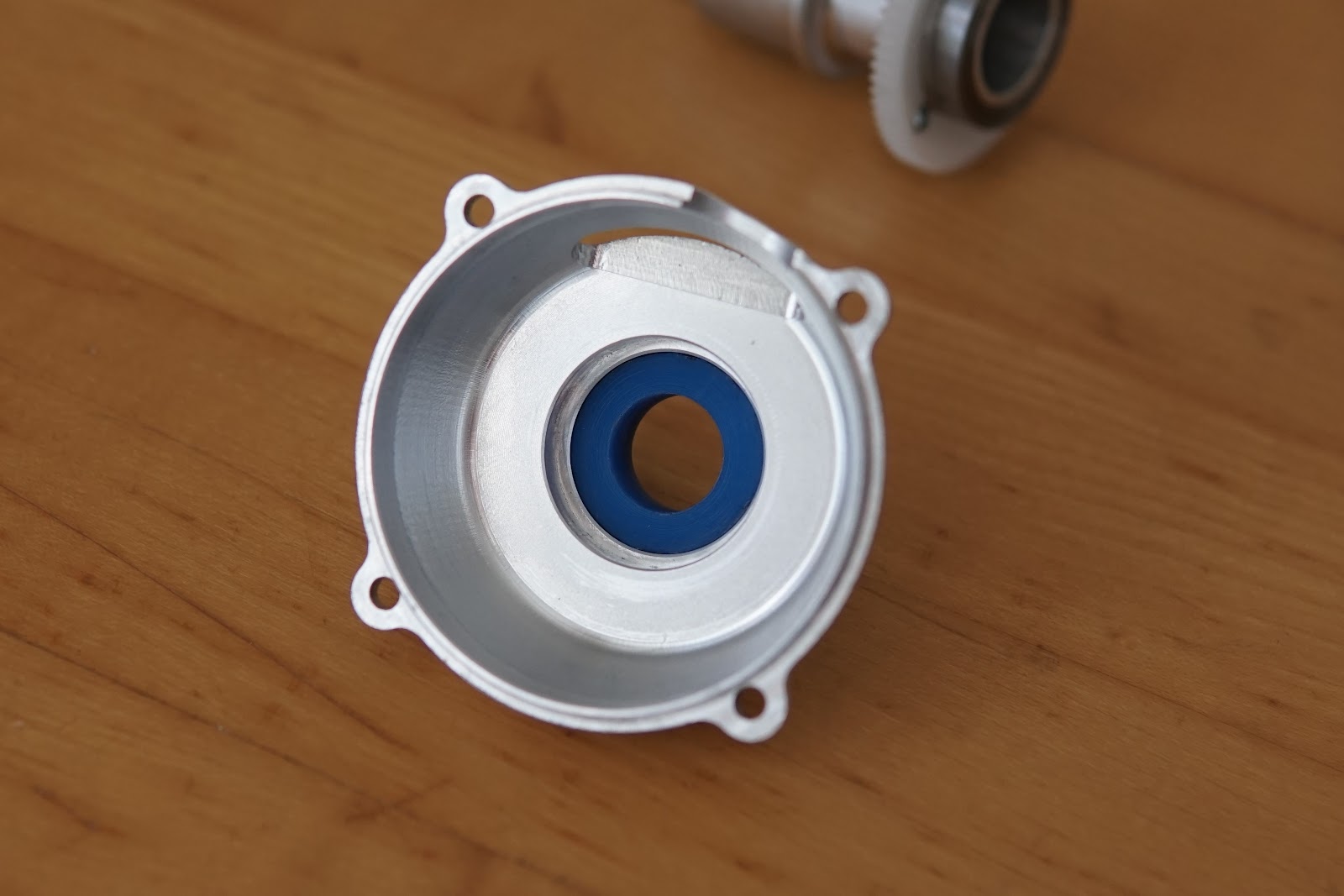
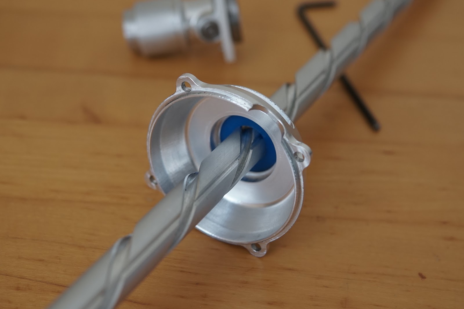
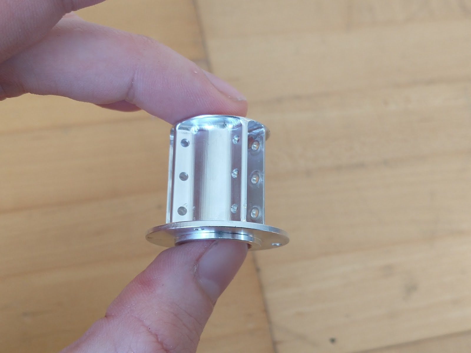
On the opposite side of the assembly from the guide bushing, there will be a set of guide rollers. There are three rollers each that run in three axial grooves along the screw. The axial grooves are shallow enough that they don't interfere with the spiral cam slots in the screw, and the 3 rollers per groove allow at least one of the rollers to always be engaged, even as the rollers pass over the cam slots.
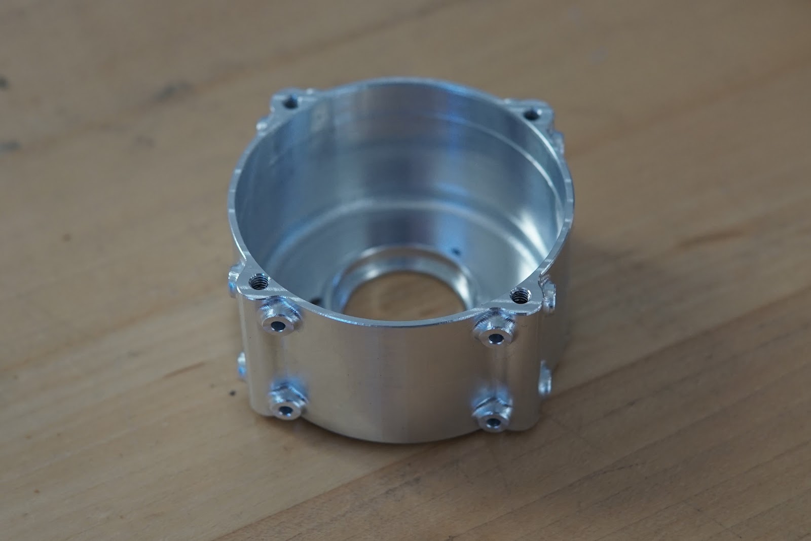
It's partially the fault of my job, and partially the fault of having a 5-axis mill at home, but all my parts are getting bad. Below is the piece that holds the nine guide rollers. It doesn't have any walls thicker than ~1.5mm, has holes bored from every which way, and has a bunch of weird undercuts.
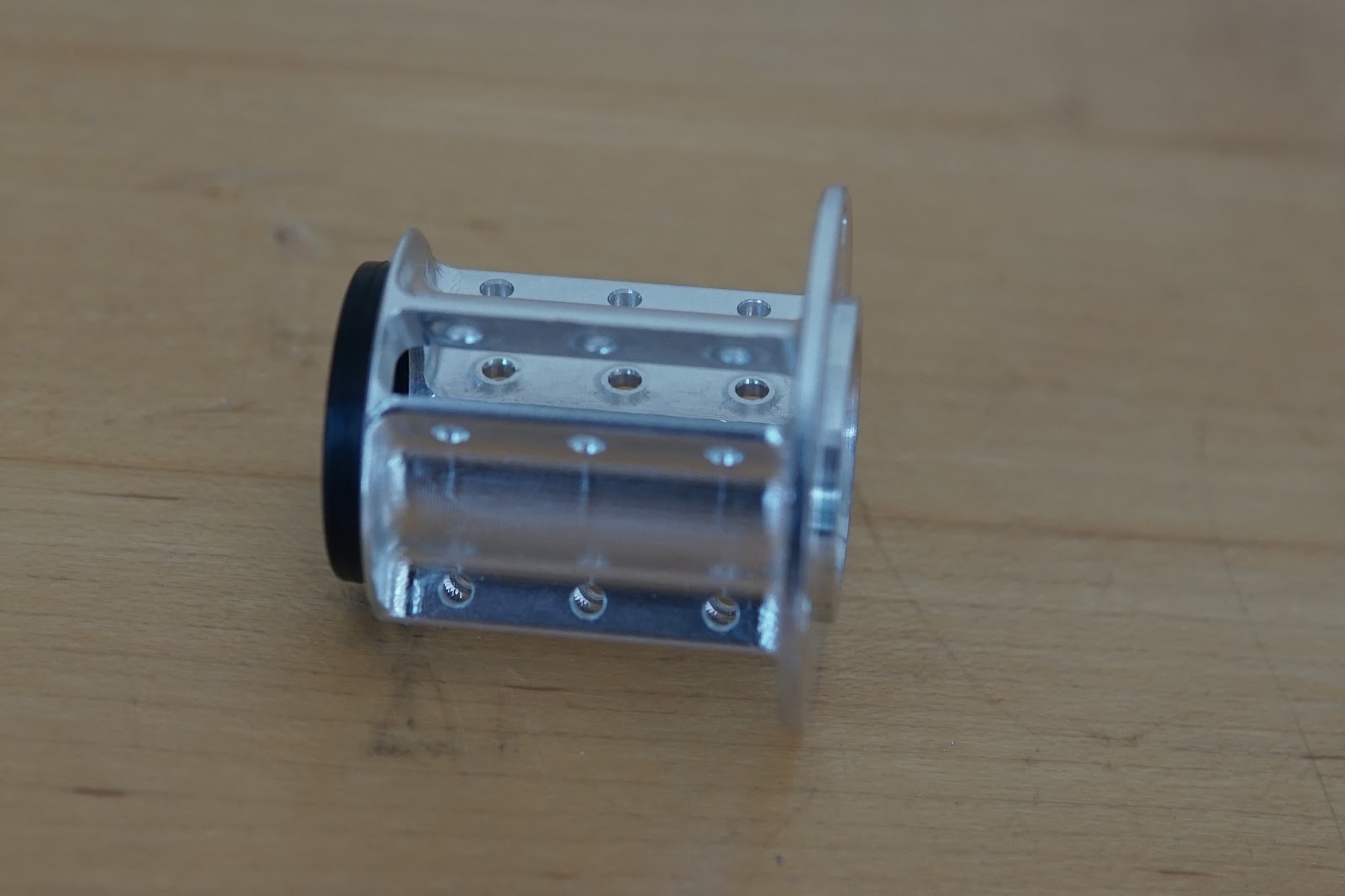
Cross section of the guide rollers assembly. The internal bosses visible in the picture above space the guide roller bearing inner races away from the walls of the part.
Here's how the part fits up to the motor assembly. The black ring at the end is another square o-ring bumper. I still need to make the guide rollers.
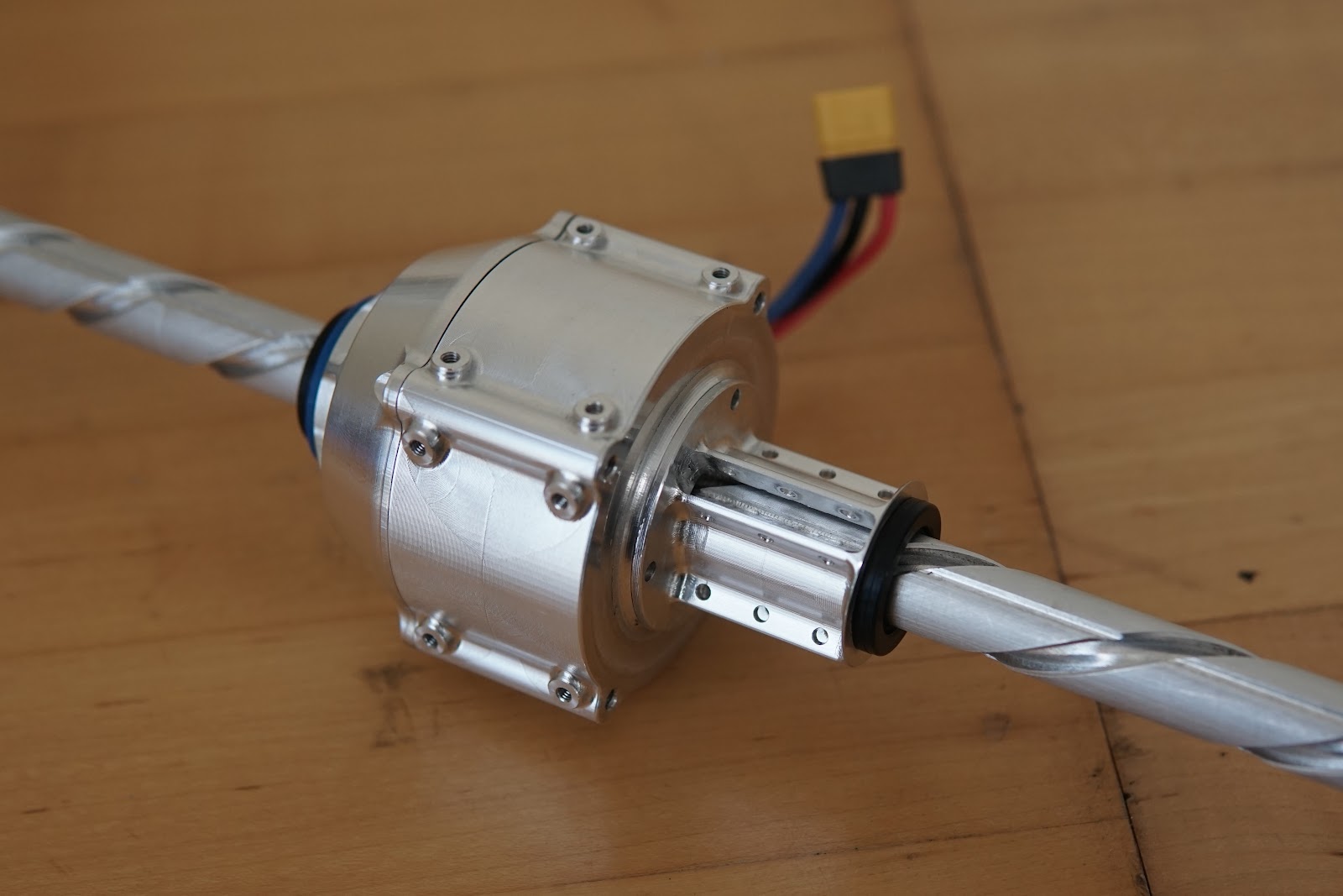
And finally, here's a view of the assembly in its current state. Just a few little parts left before it's ready for some testing - not jumping to start out, probably launching something of equivalent mass. Either something's going to get launched very high, the mechanism is going to explode, or both, so it will be exciting regardless.
Comments