Trike Revival for the BD Car Show
Robot land has an annual car-and-other-vehicles show. Last year I brought the hybrid car powertrain go kart, but this year the kart's geting some upgrades (stay tuned), so I brought the electric tricycle instead.
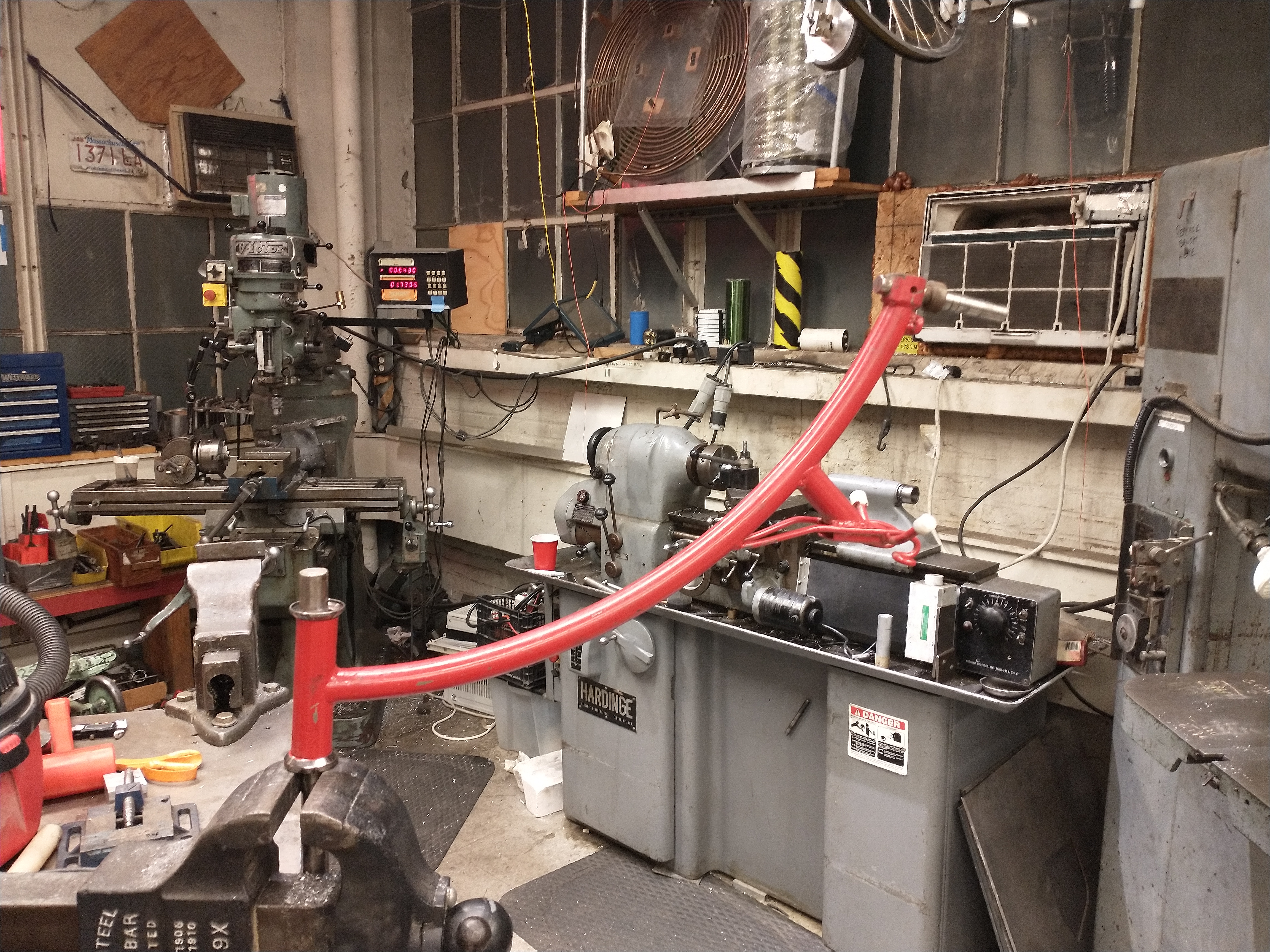
The trike has been hanging from a miters wall unused since 2019. The last time it was ridden, someone crashed it into a curb and bent the head tube inwards, so it needed some work to get back into a rideable state.
Somehow it's been ~11 years since I built the tricycle - looking back at the blog to jog my memory, this was one of my first big projects at miters, one of my first projects using a mill and lathe, and the first thing I ever designed in Solidworks. It's a miracle it worked.
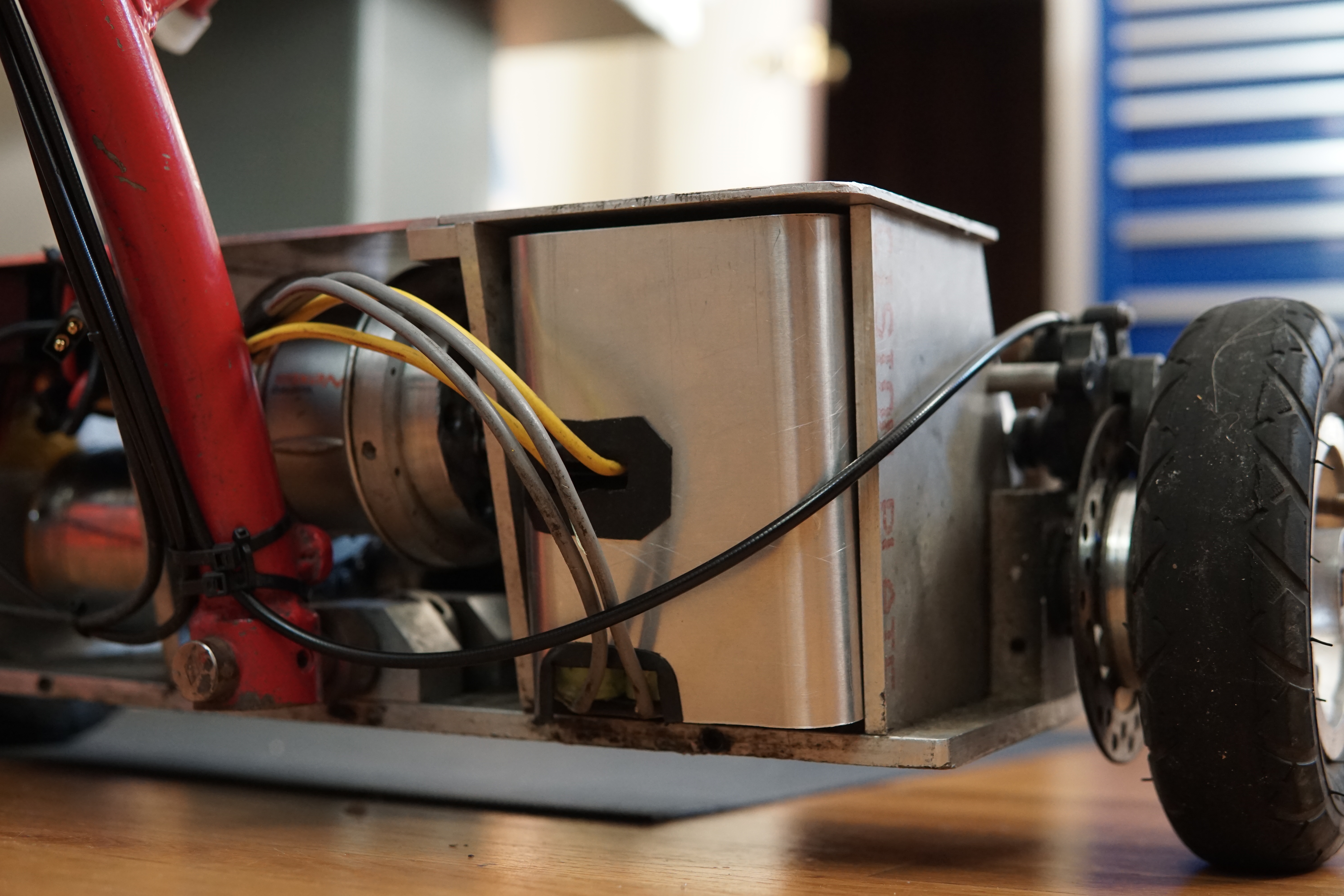
Here's the trike pulled down from the wall. The battery cover broke ages ago so the battery is strapped in with tape. Most of the wires are held together by duct tape. The brake and shifter cable housings are frayed, and 5th gear sounds super crunchy. And that head tube angle...
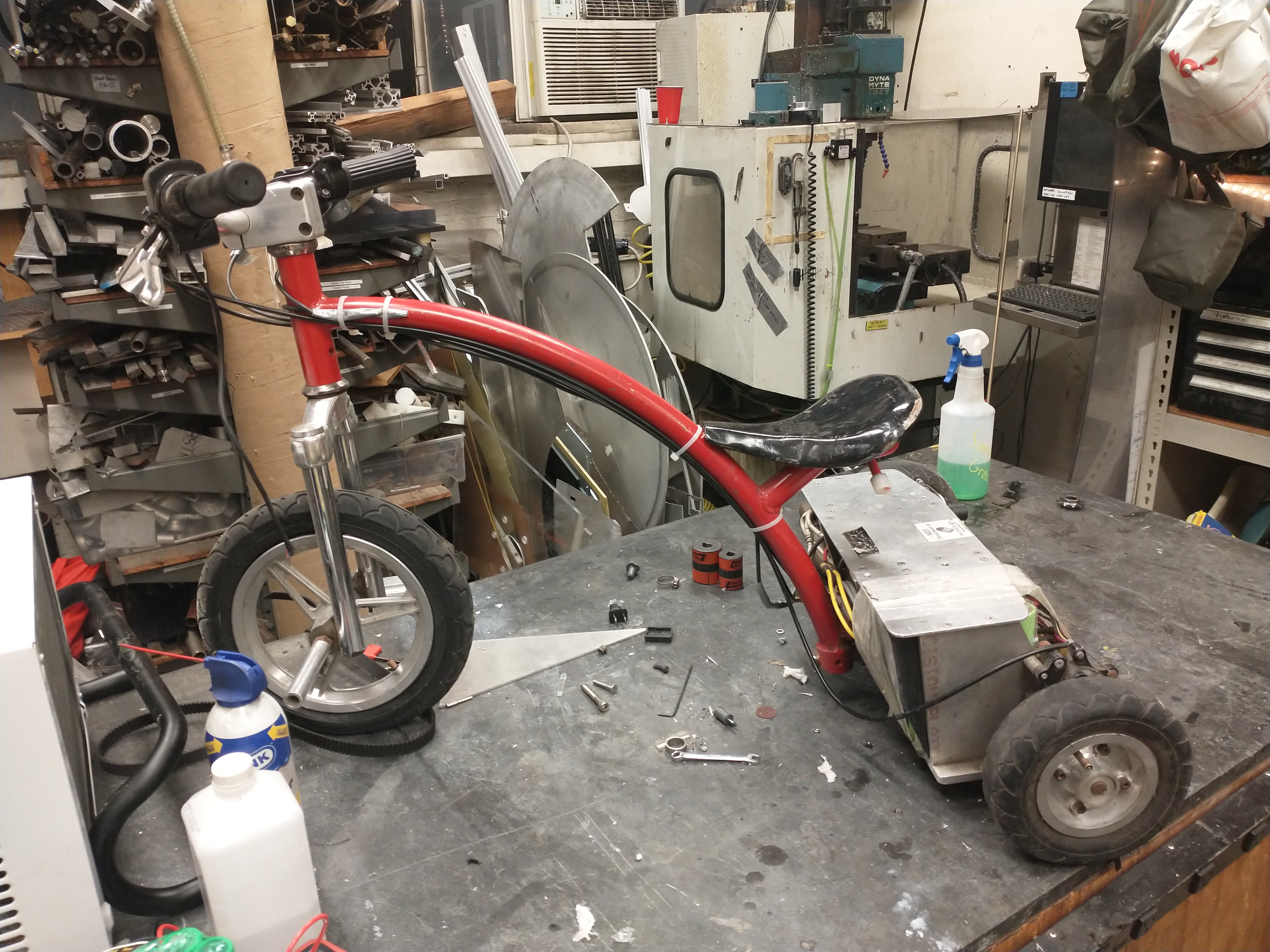
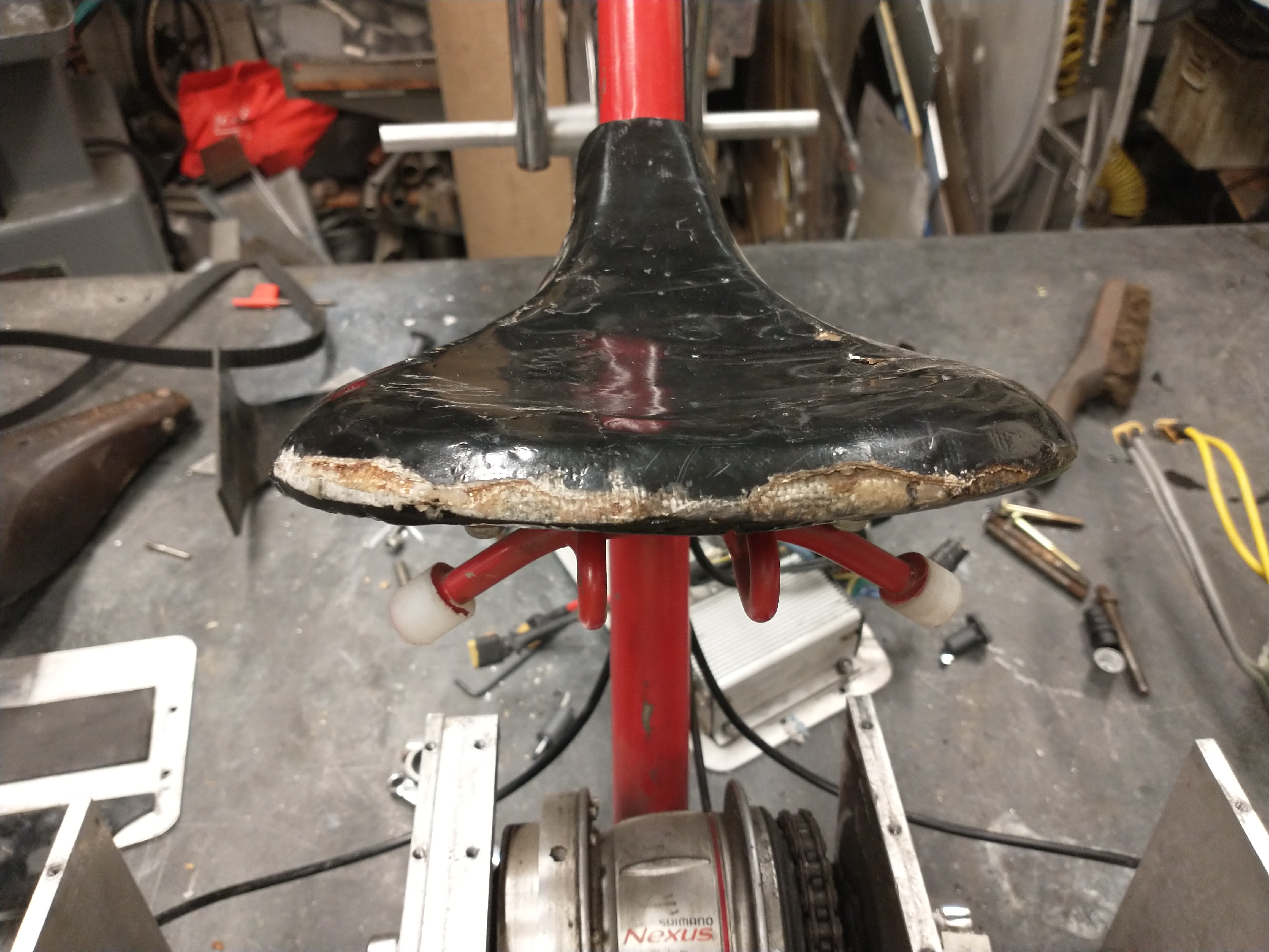
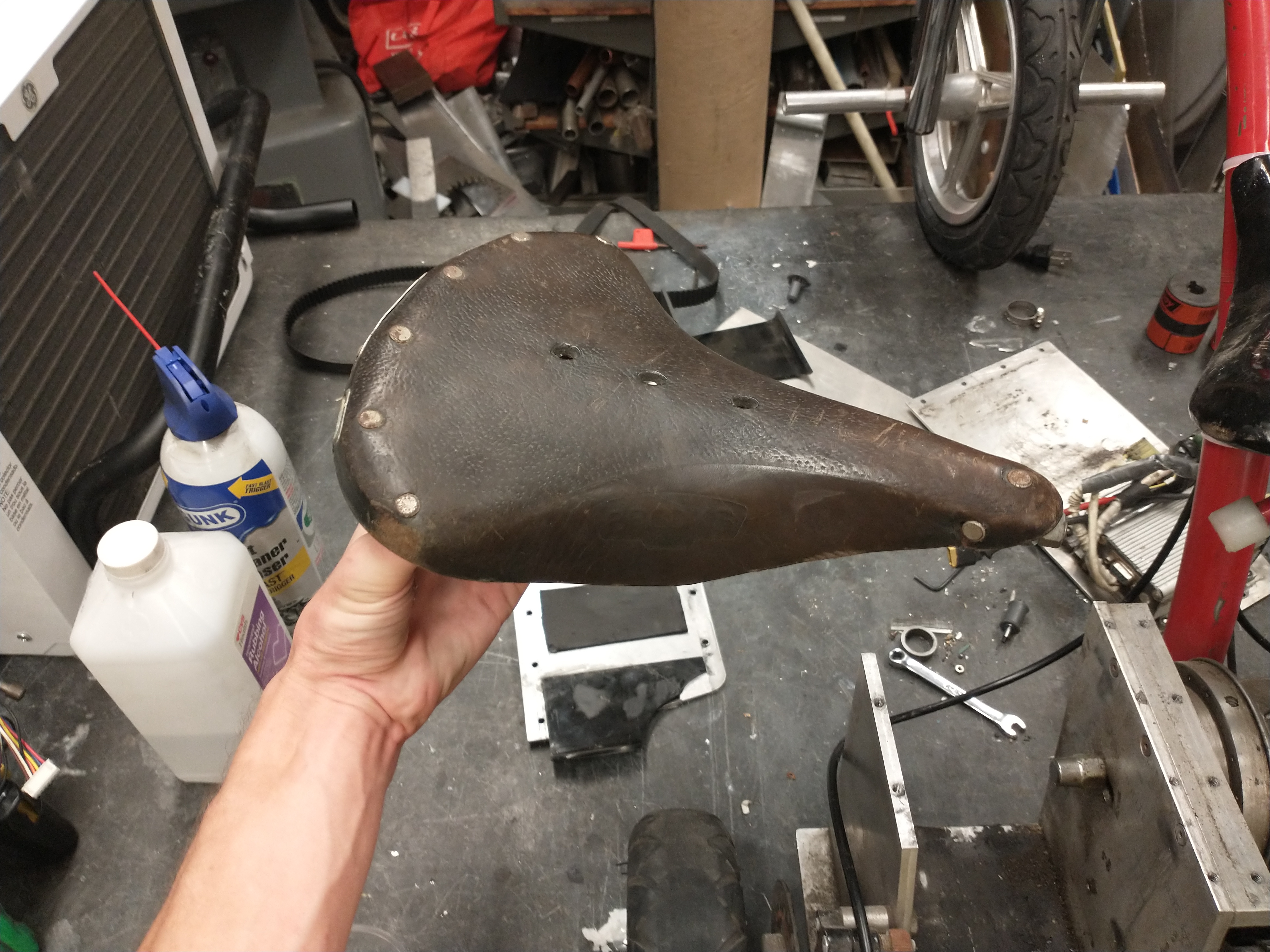
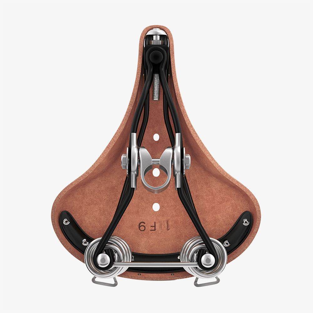
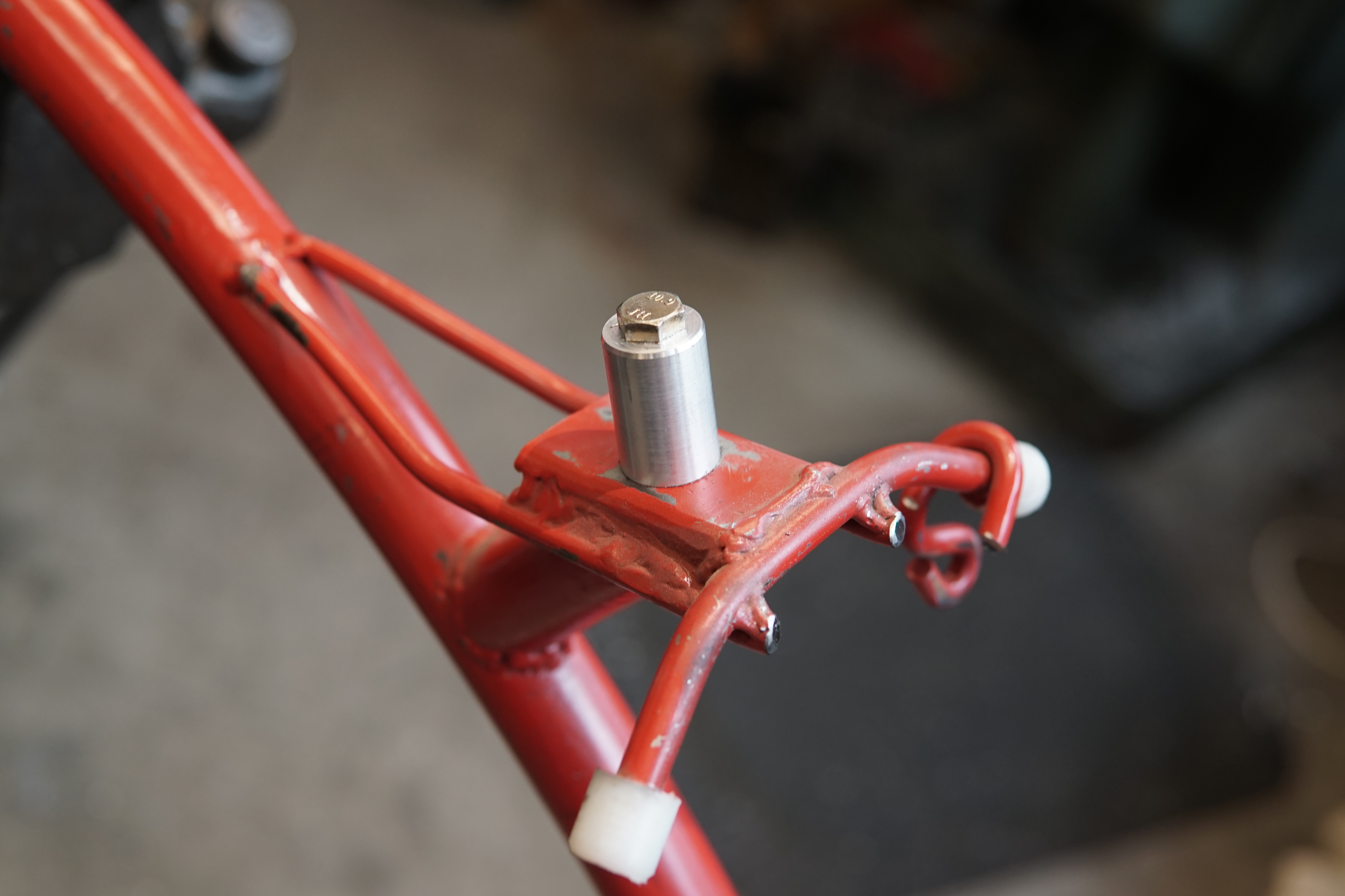
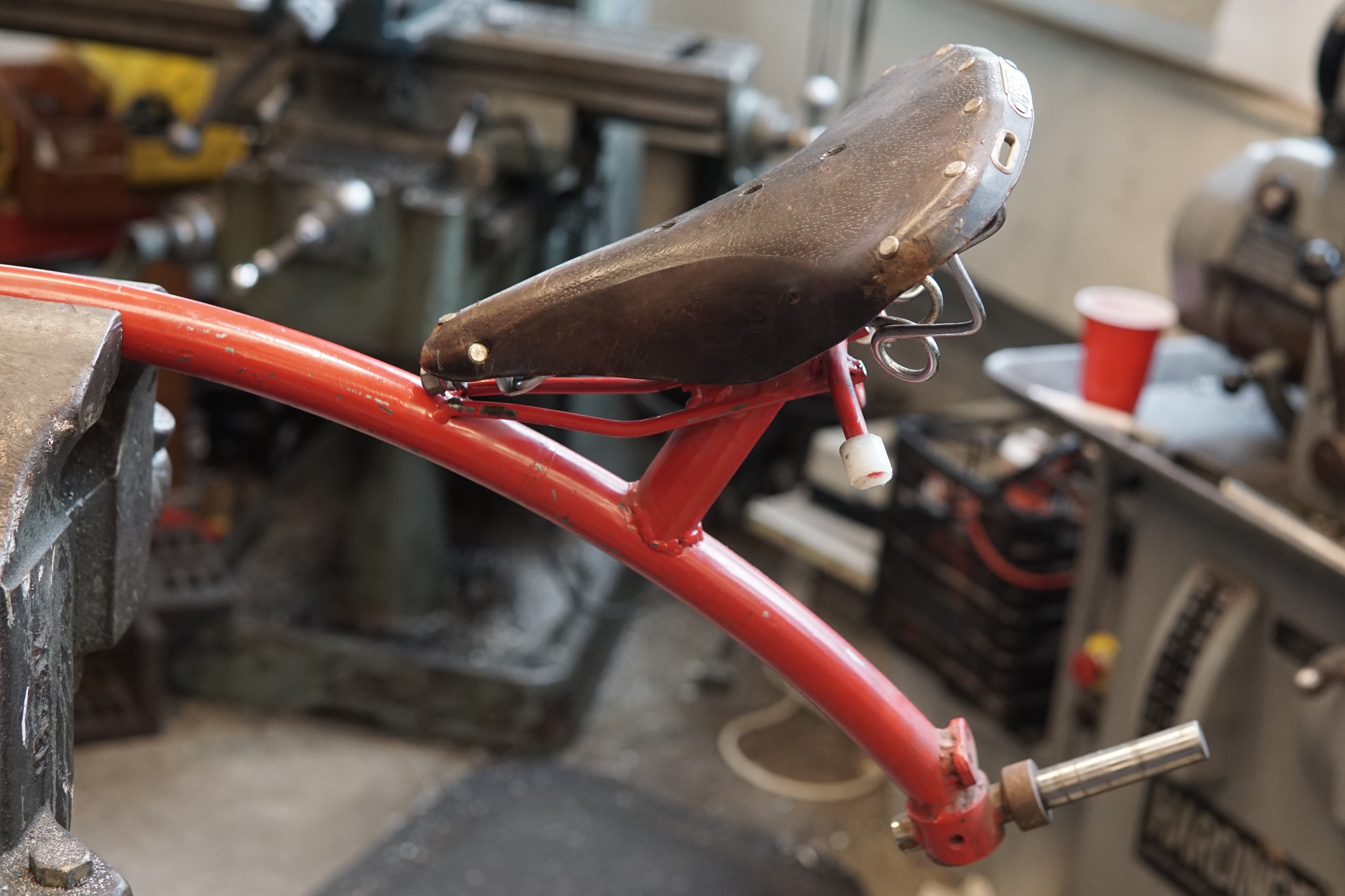
The trike wasnt bult with swapping seats in mind - I welded the rails of the original bicycle seat straight to the frame. This Brooks saddle uses a funny double-rail mounting system where the clamp is built into the saddle, rather than into the seatpost like normal. Instead of welding more stuff to the frame, I turned a little seat post stub and bolted it on:
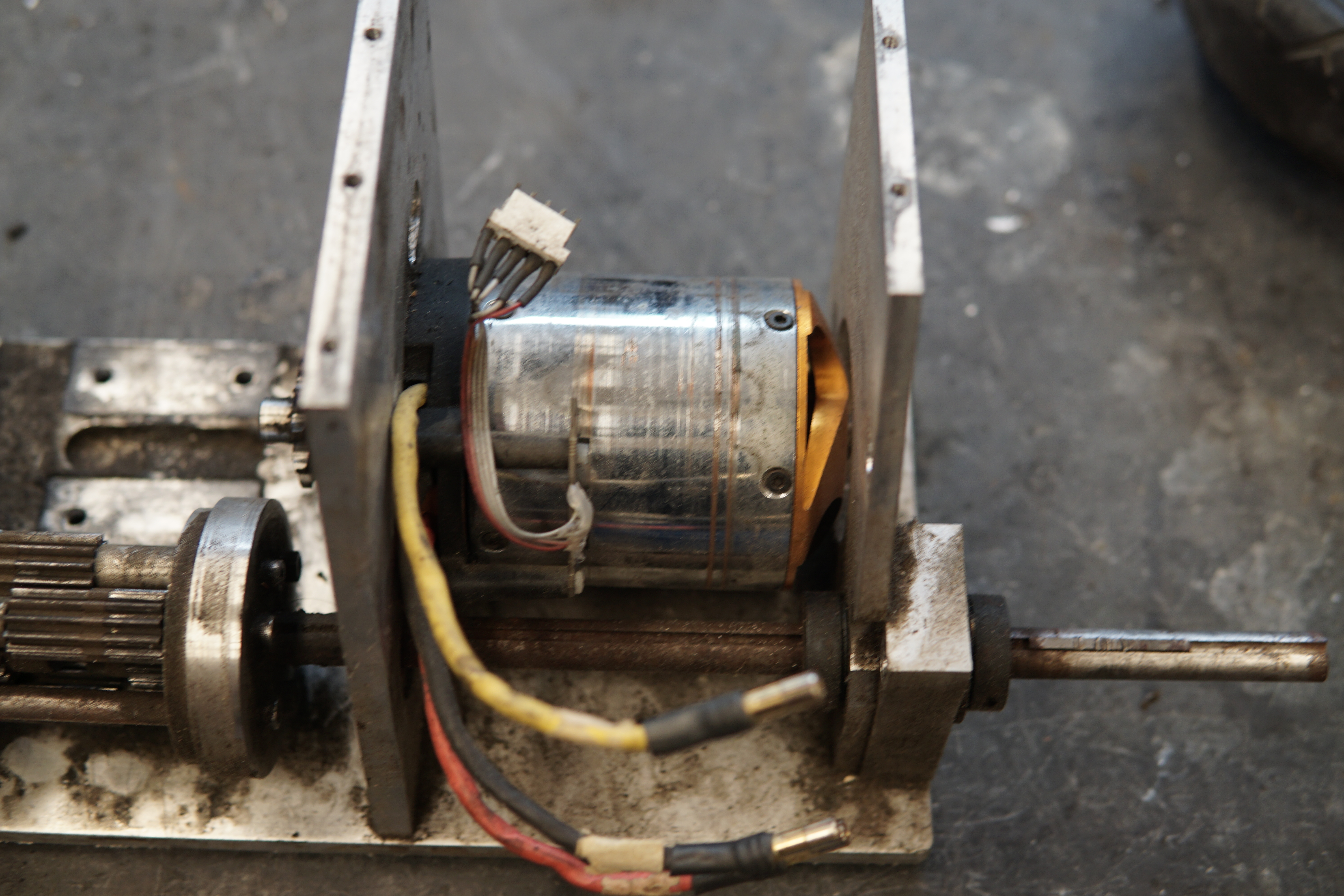
I brought the pile of parts home from miters and did the rest of the repairs in the home shop. I got this cheap e-bike controller shaped VESC as a replacement for the Kelly - it's not higher power, but supposedly supported external SPI encoders, and a real encoder + FOC should be big improvement over the old hall sensor and trapezoidal drive setuop. It claims to be a 120A max controller, but I've only gone up to 75A so far - internally it's just got 6 TO-220 package FETs, so I'm probably not going to push it much further:
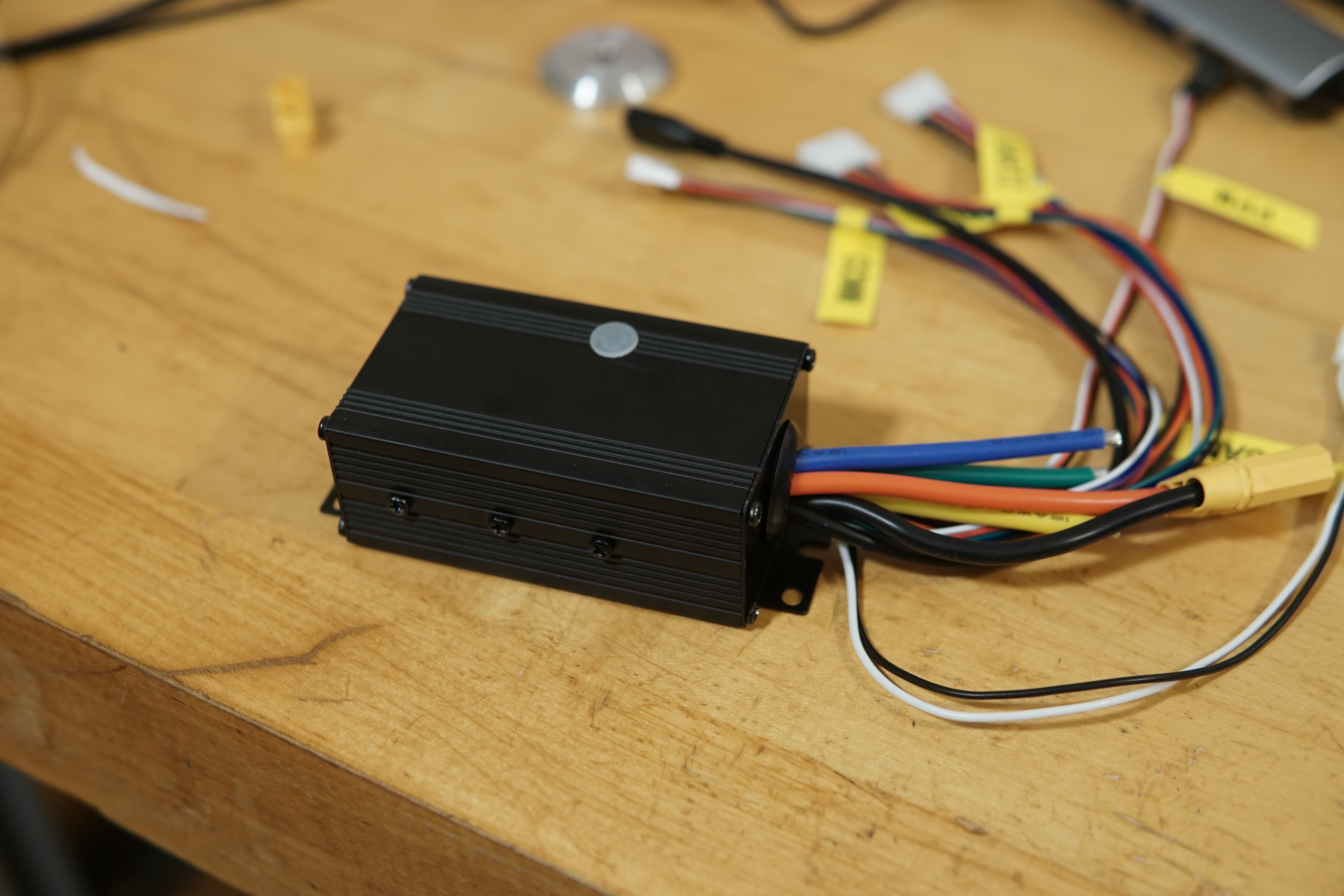
Turns out the controller didn't really support external SPI encoders. I wired up the encoder to the hall sensor cable according to a guide I found online, but it didn't work. Probing around with a scope, the signals looked nothing at all like SPI.
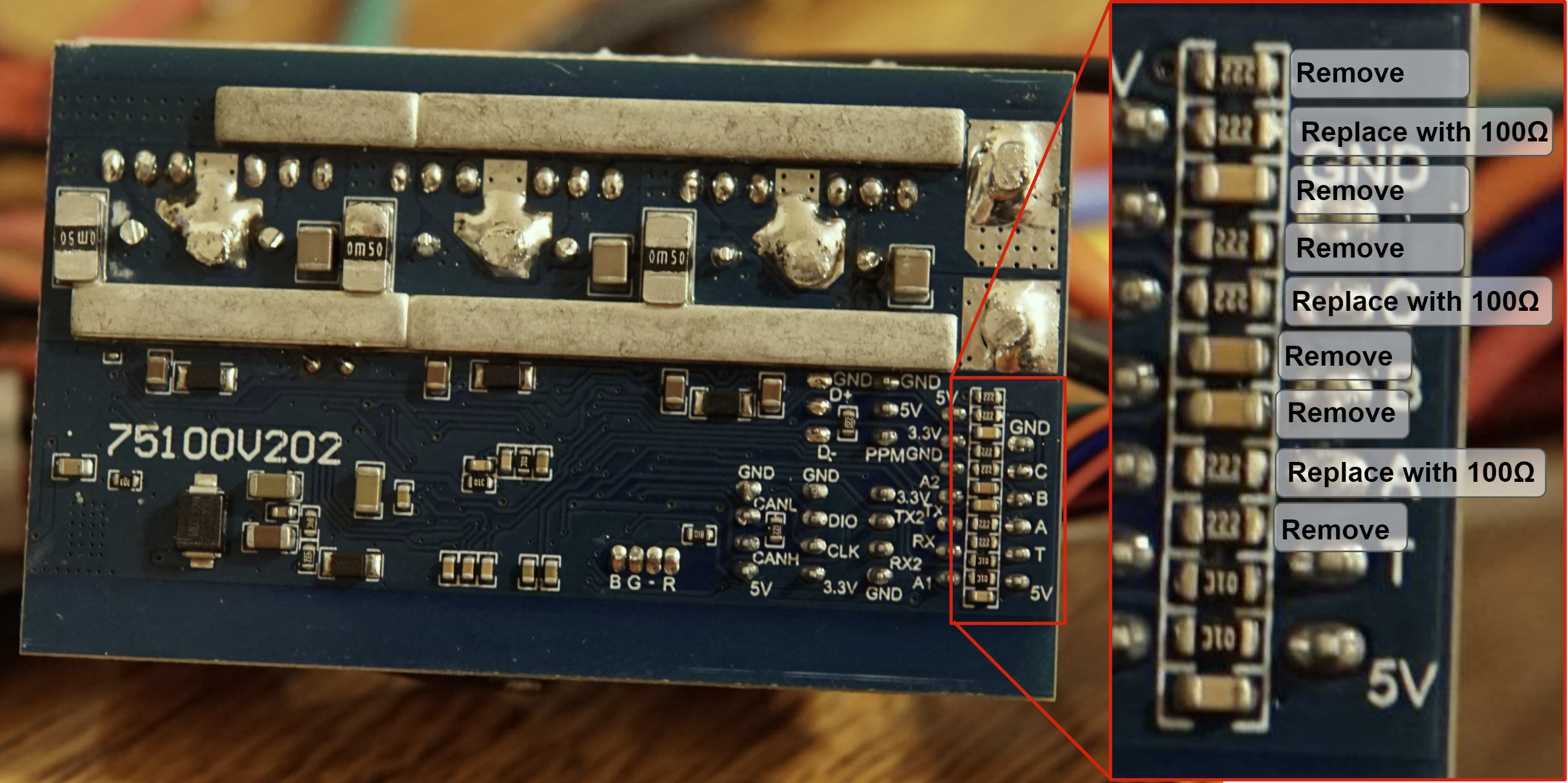
I cracked the controller open and immediately found the problem - there were RC filters and pull-ups/downs on the pins, for hall effect sensors. More probing around and I was able to figure out what modifications to make - the picture below shows the full set of changes I made to the drive. Initially I had solder bridges instead of the 100 ohm resistors, but I found that the SPI only worked when I was scoping the clock pin - I gues the tiny bit of capacitance from the scope probe was damping out some ringing edges. The 100 ohm resistors in series fixed everything.
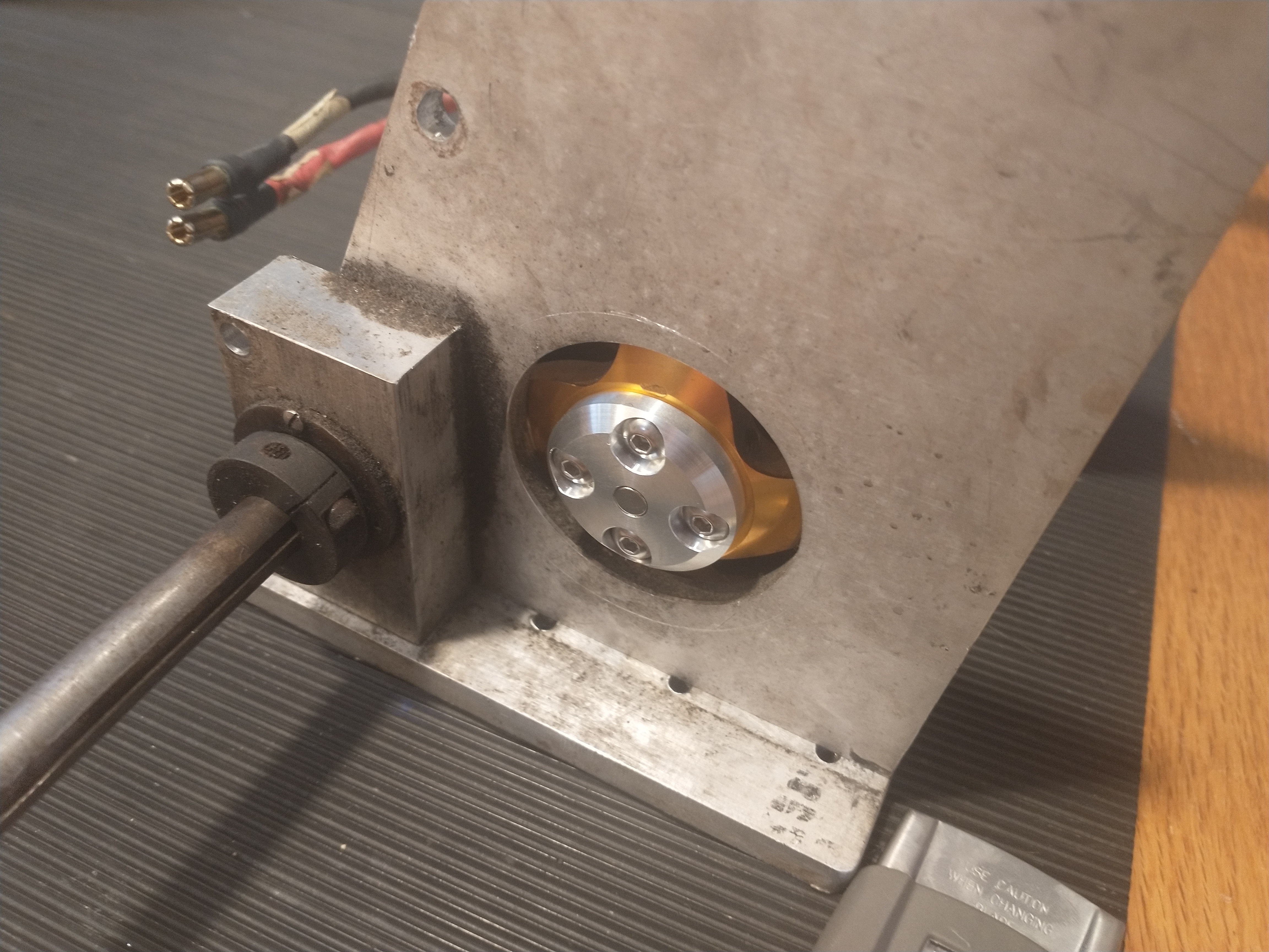
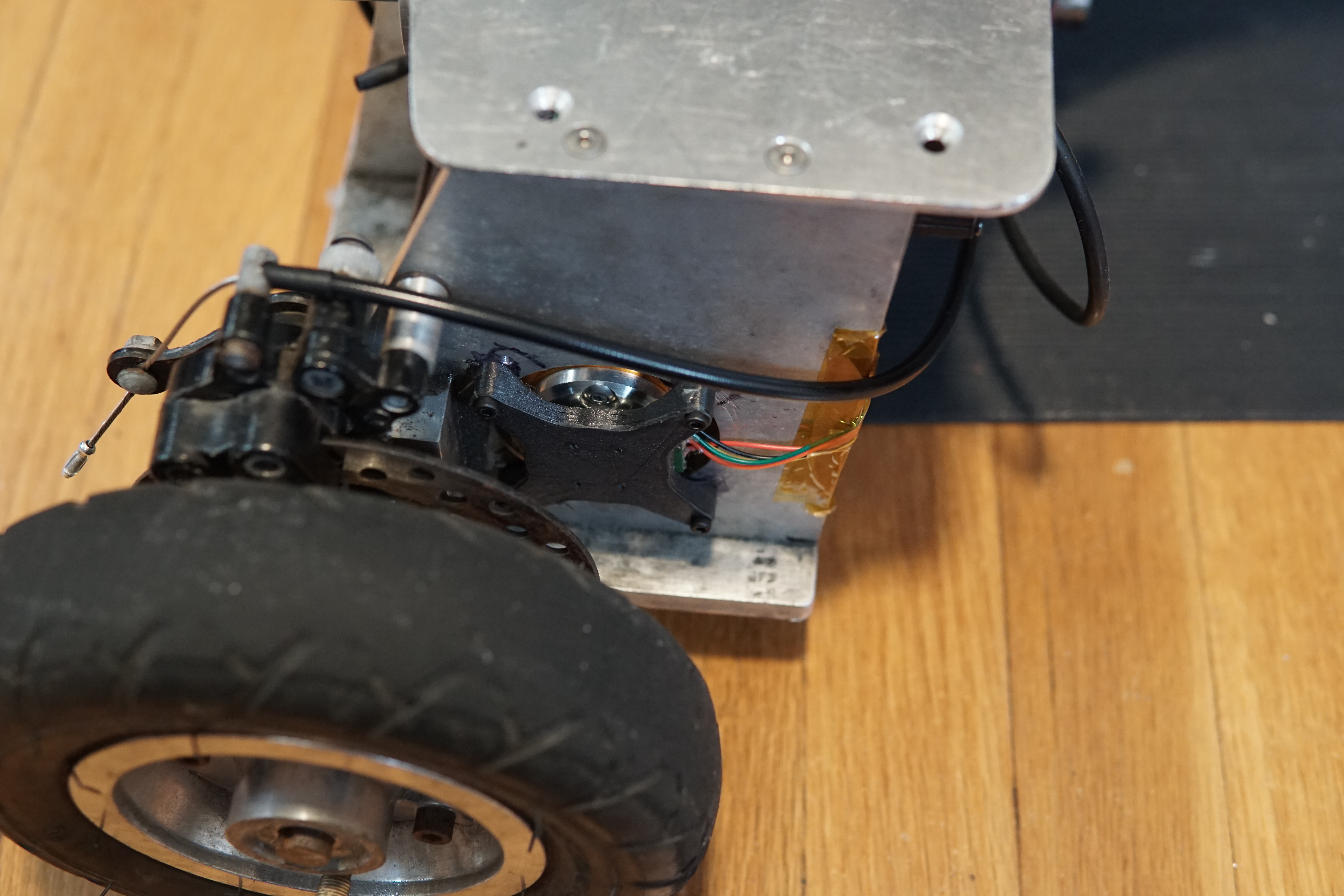
And 3d-printed a holder for an encoder breakout board:
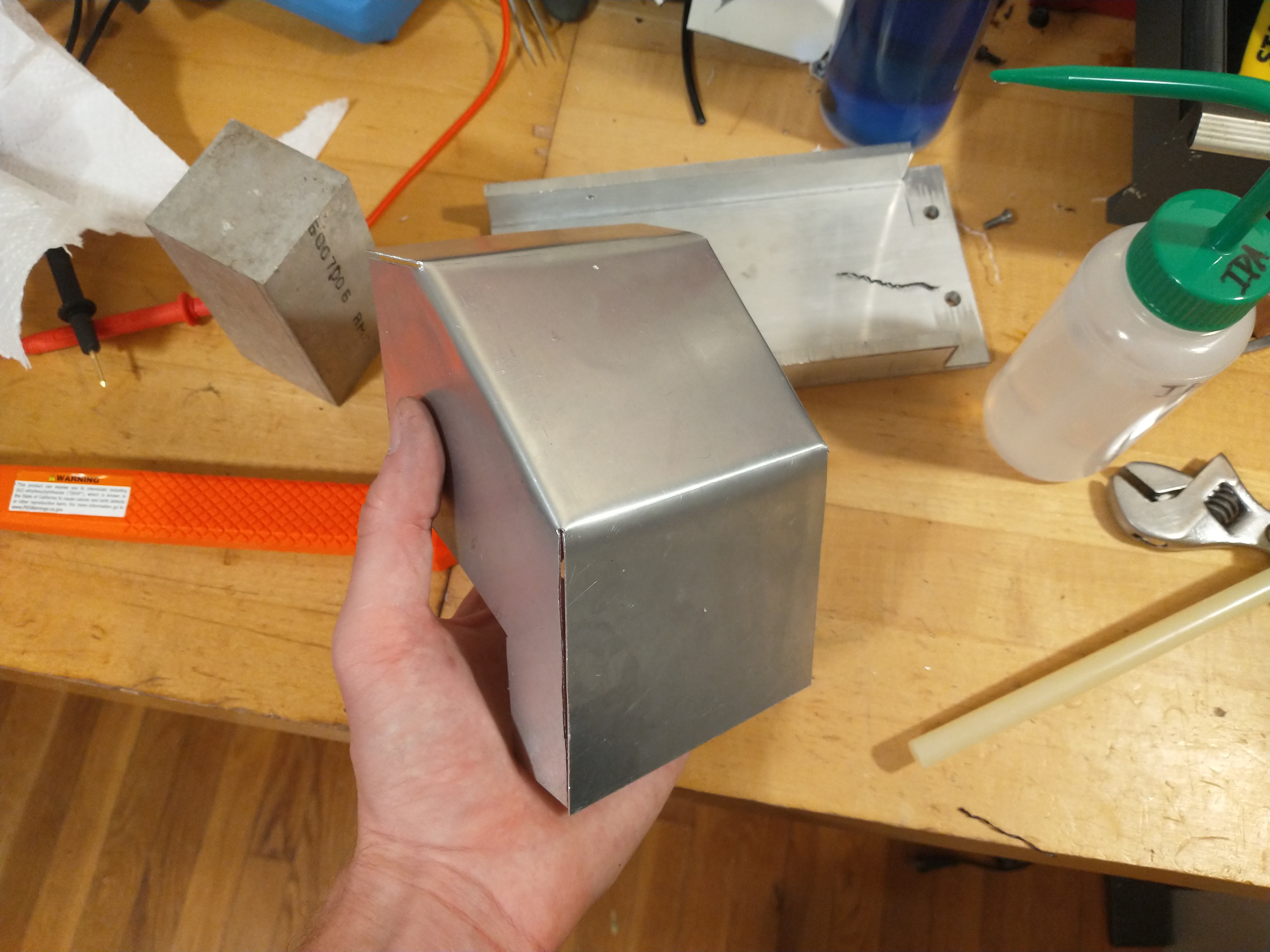
The original plastic battery cover got destroyed ages ago, so I did some CAD - the other CAD - and whipped up a new one out of some thin aluminum sheet.
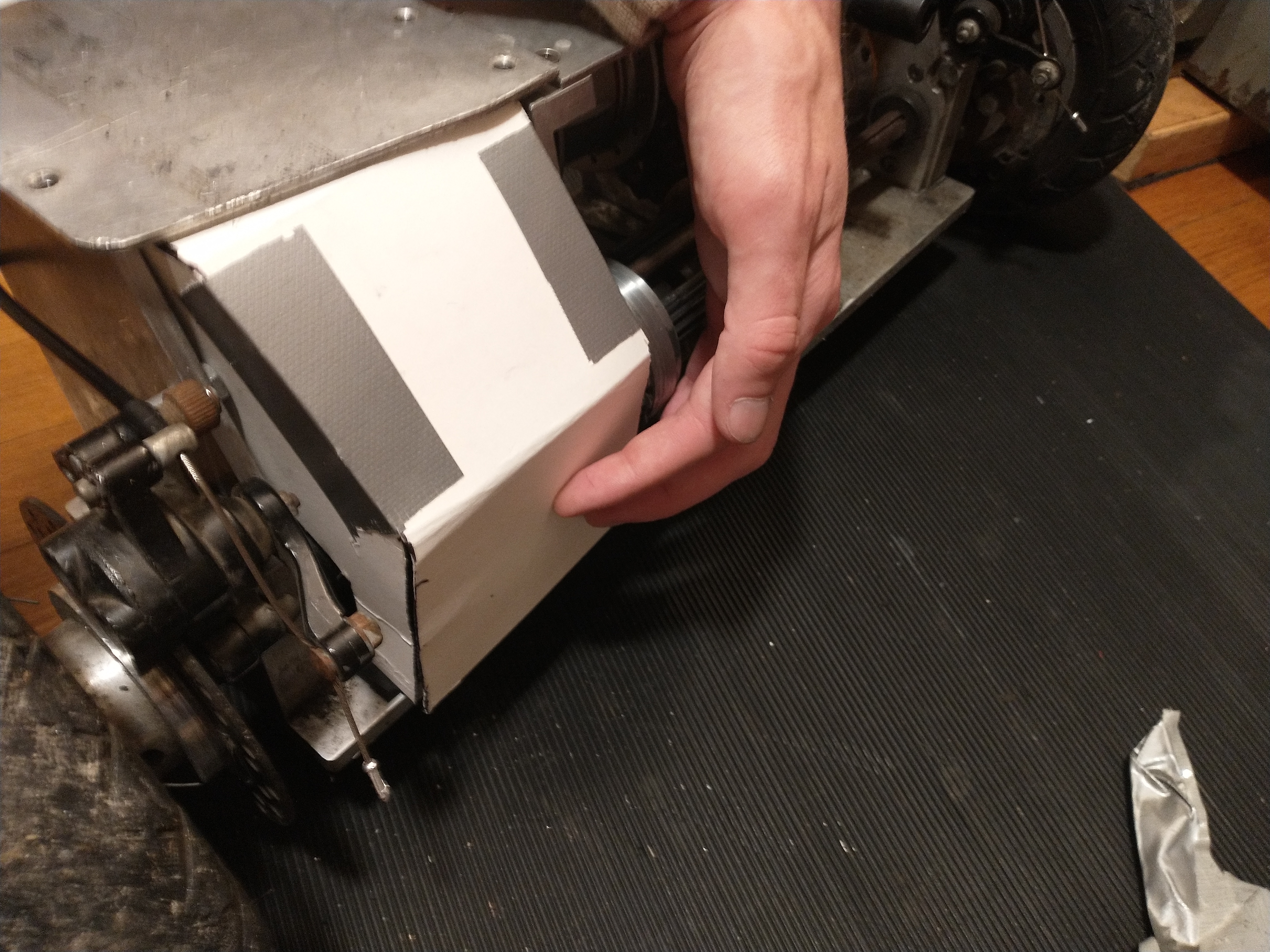
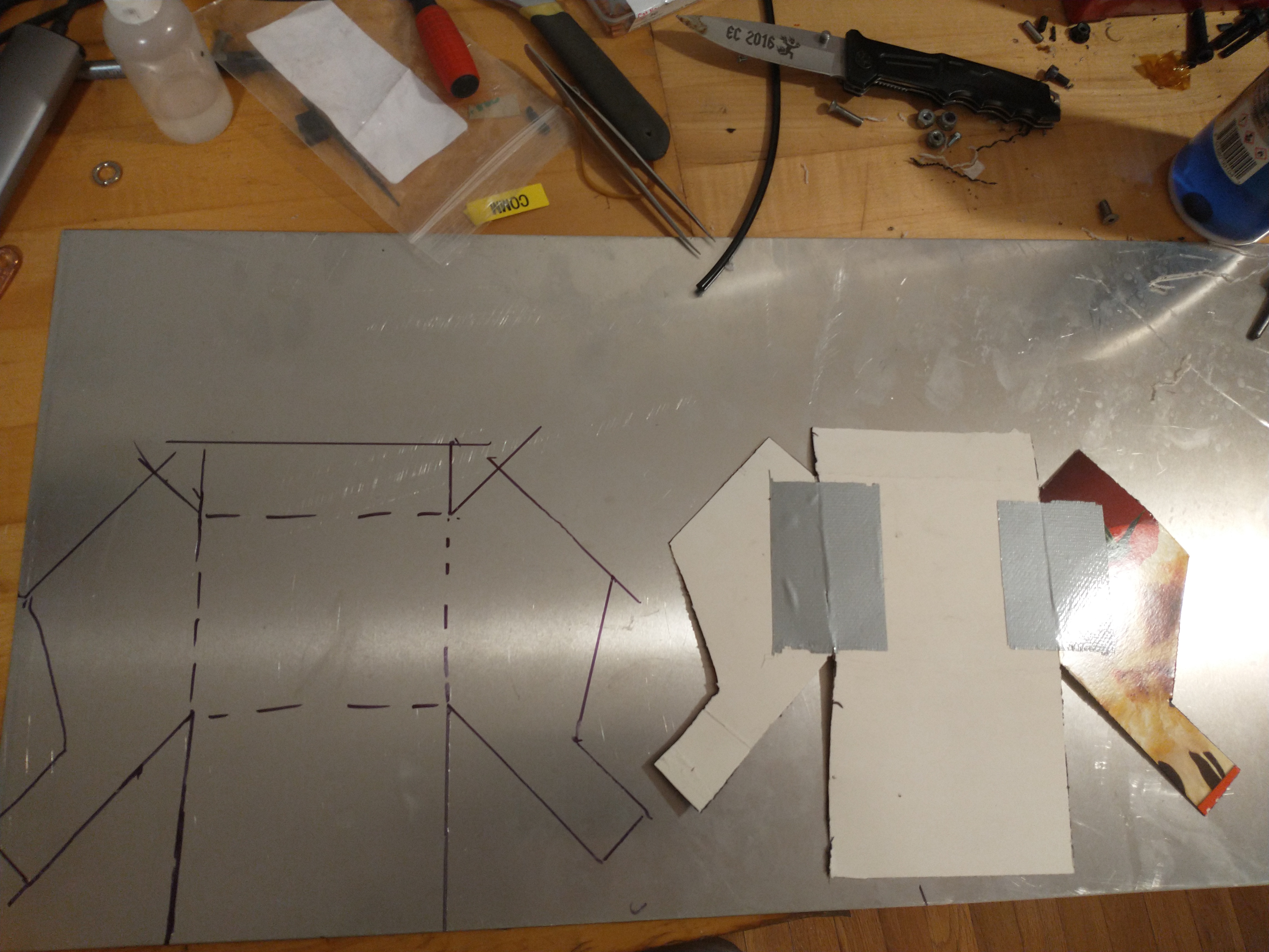
I don't have any sort of bending brake, so the sheet was bent with a combinations of quick-grip clamps and aluminum billets.
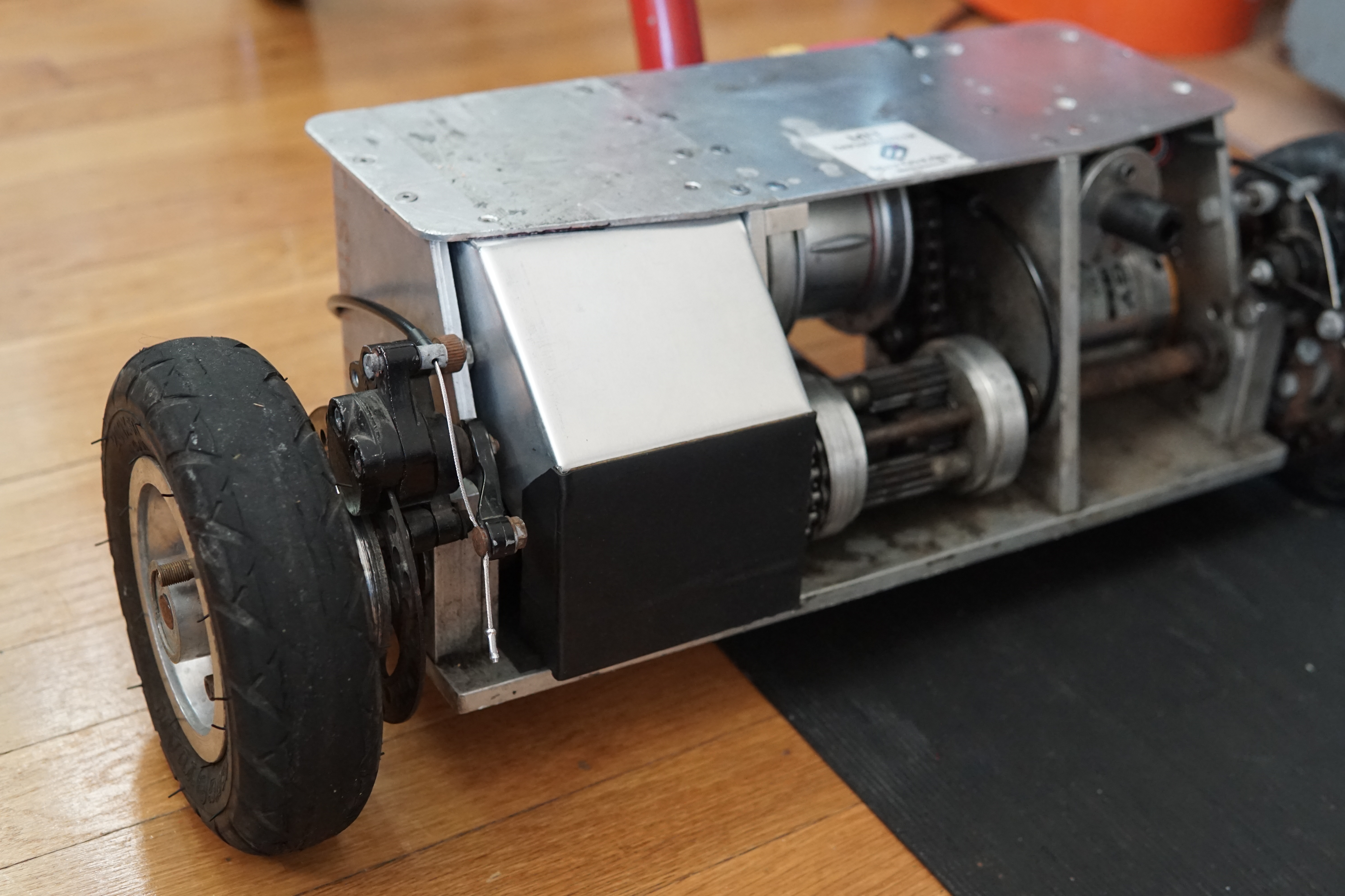
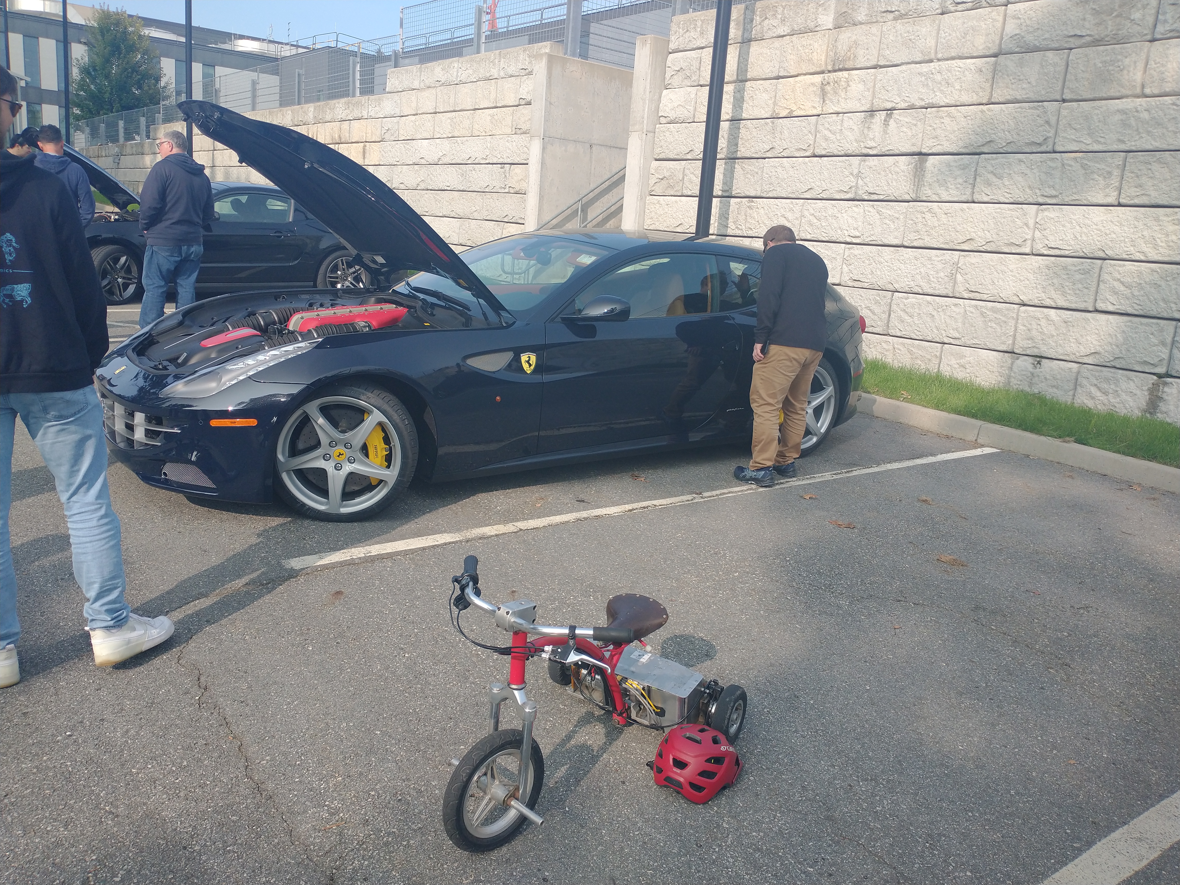
I didn't take many pictures or videos at the show itself, but parking it next to a Ferrari wagon (I can't beleive that's even a thing) was entertaining. Lots of test rides with no issues other than a set screw coming loose once. It could definitely use a bit more motor controller - it's noticeably less peppy than before (with a 120A limit on the Kelly controller).
Comments