Go Kart Revival Part 1: Drive Units
As I've mentioned in previous posts, robot land has an annual car-and-other-vehicle show. Last year I brought the trike, but the year before that I brought the electric kart I worked on with Bayley.
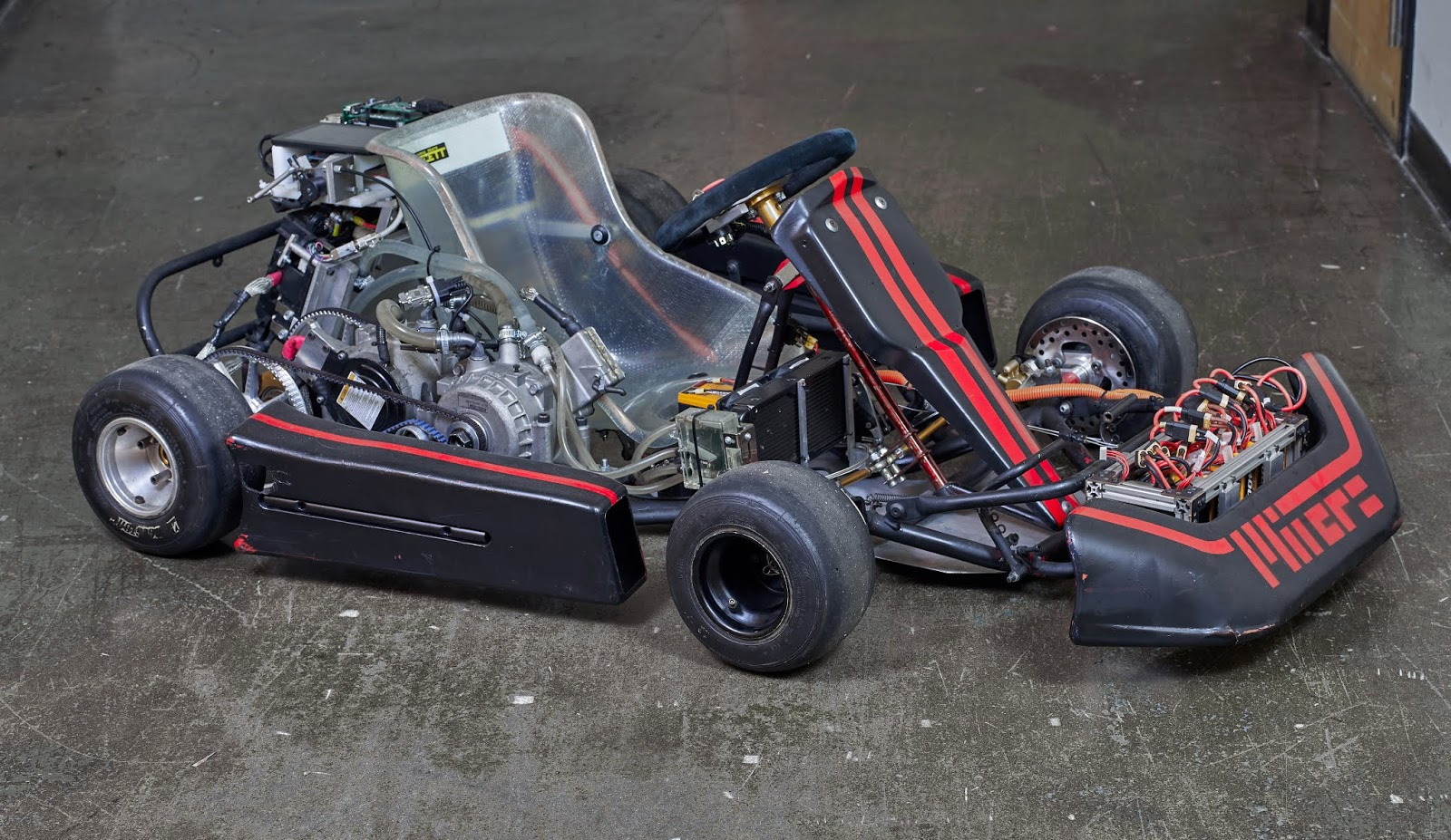 |
| Picture from Bayley |
Before the event, the kart hadn't been touched since the pre-Covid days. Bringing it back to life and ripping around the parking lot was a great reminder of two things:
- This thing is so much fun to drive.
- Thing is so janky
One feature I wanted with this upgrade was independent control of the rear wheels rather than a solid rear axle - so I can do fun traction control stuff in the future. There are some complications making this work well on a kart chassis (which are designed around solid axles and jacking up the inner wheel around corners), but I have plans to deal with that I'll explain in some other post. I explored a few different layouts for independent drive units - sticking with belts and single-stage spur or helical gear reductions were the two main other candidates - but a pair of planetary drive units in-line with the rear axle looked the most promising.
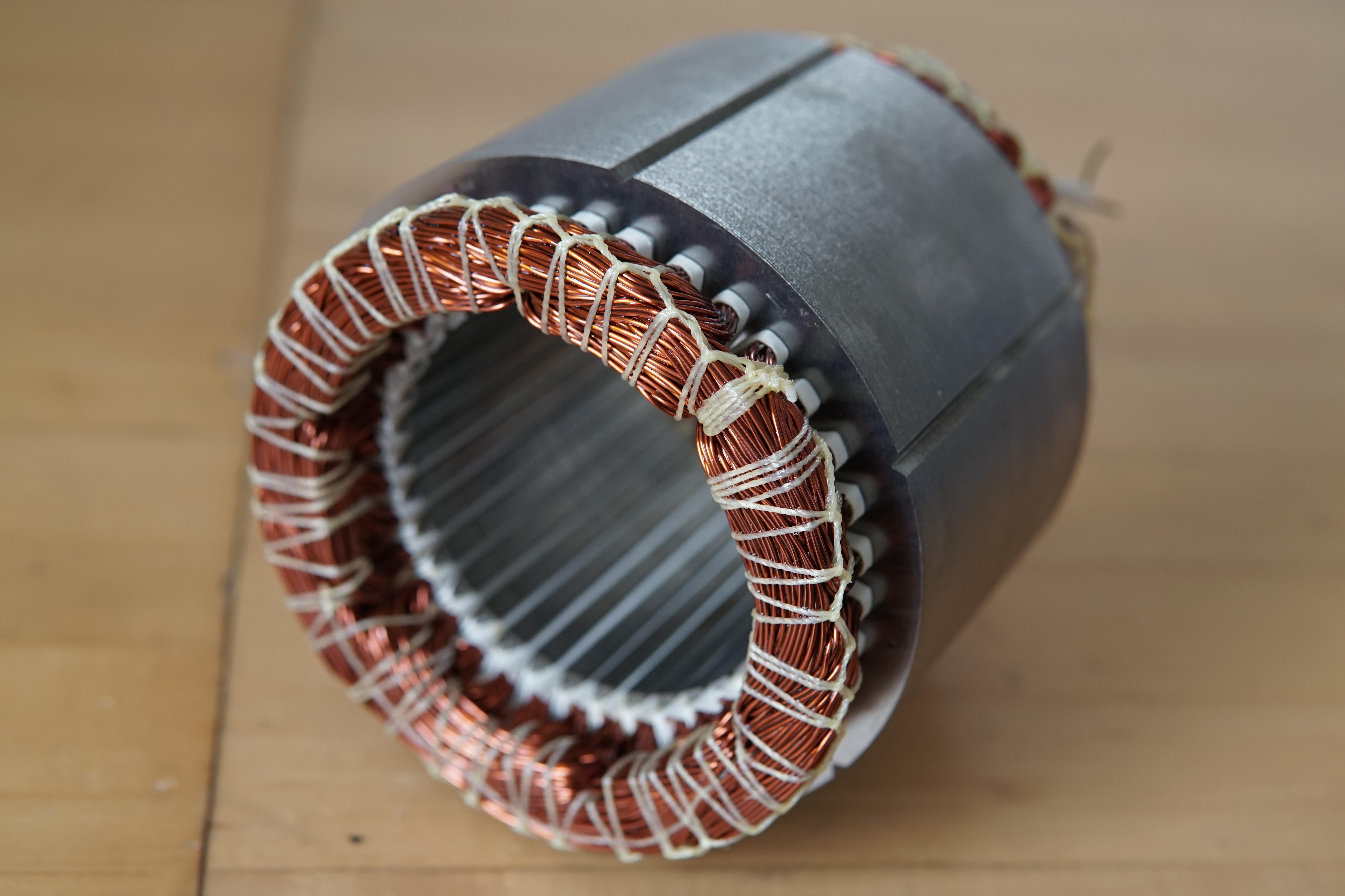
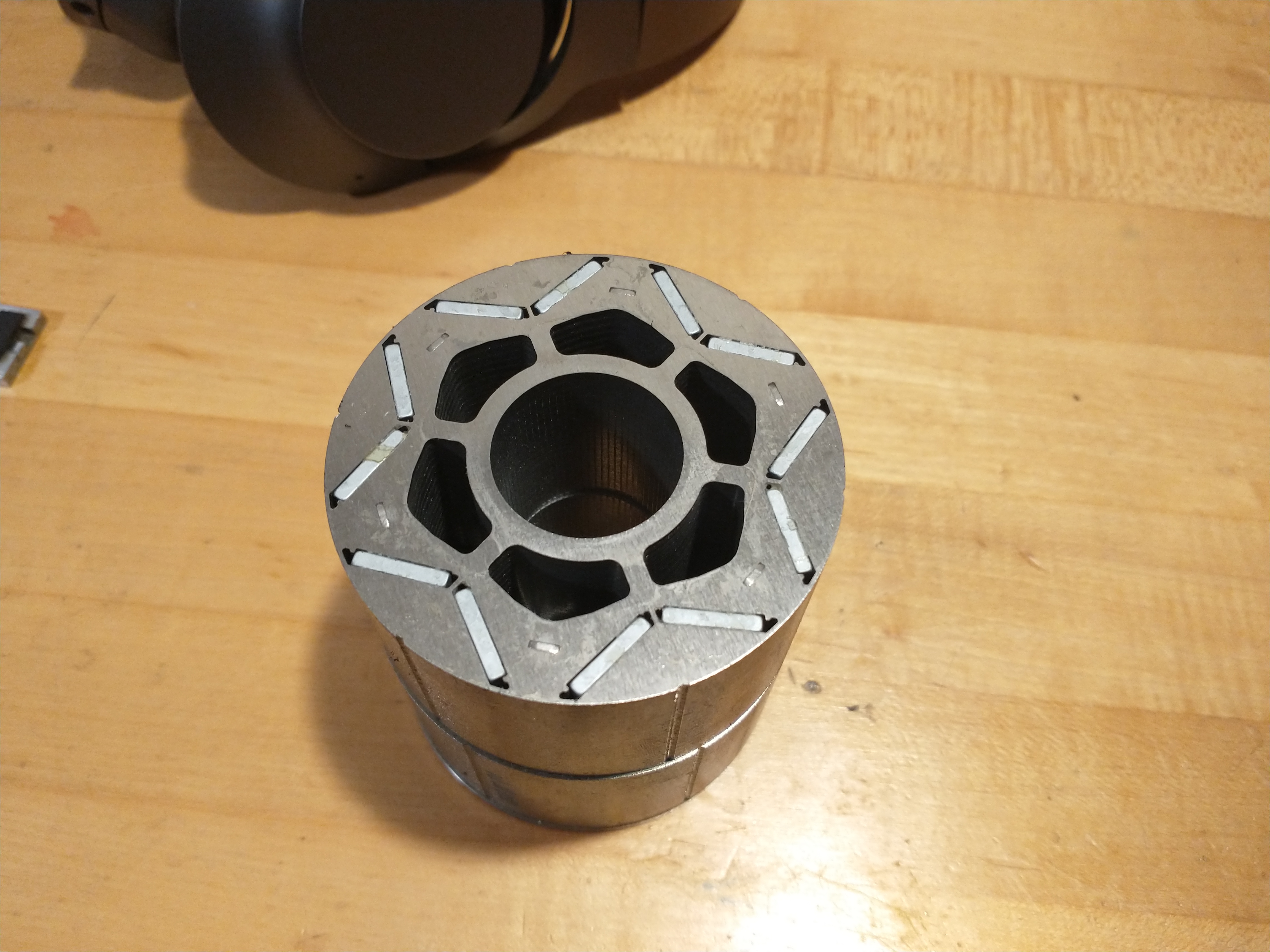 |
| V-magnet arrangement rather than flat magnets like the 2012 HSG |
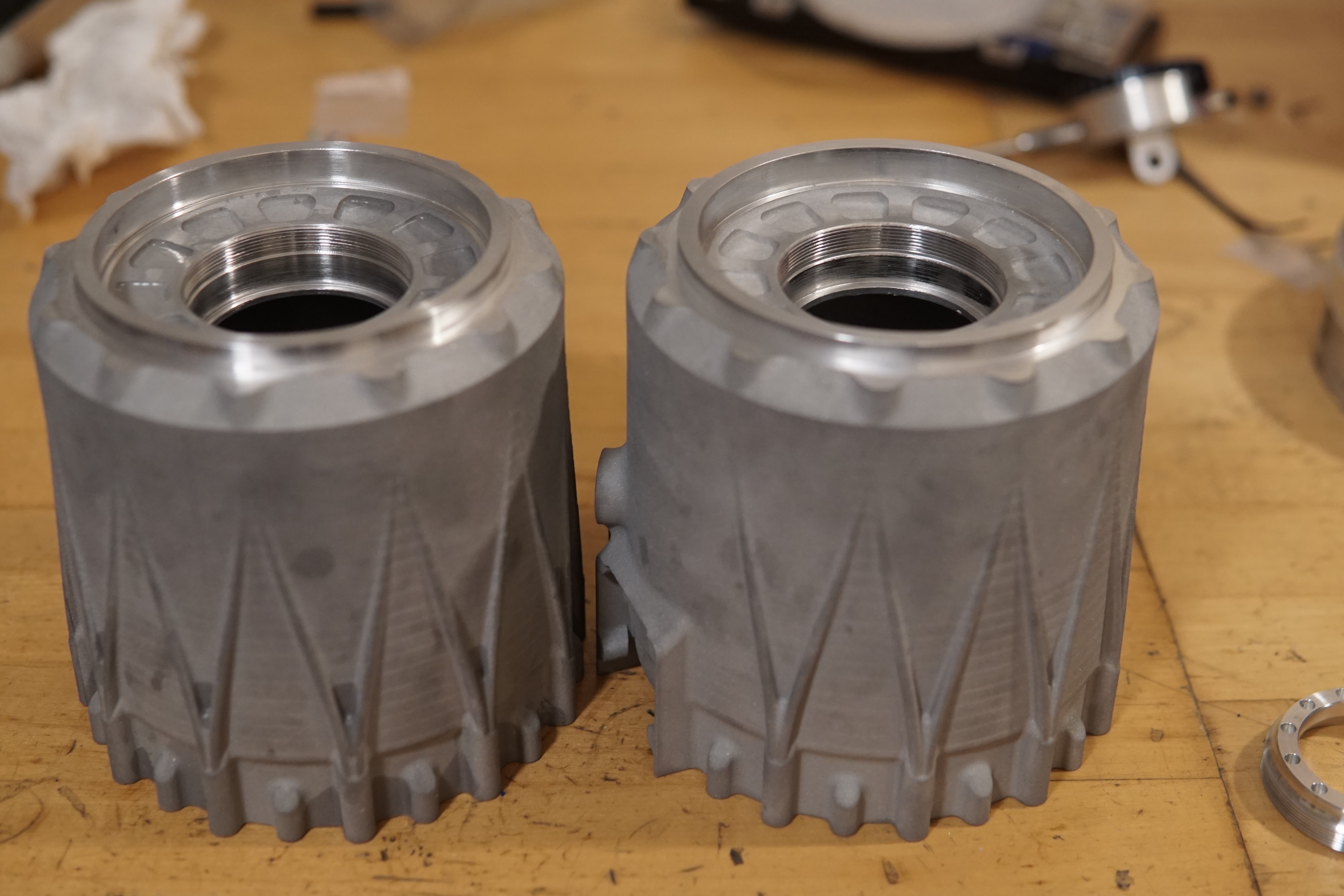
I looked into a few different options for planetary gears and ended up buying some chinese industrial servo planetaries in the hopes I could modify them to work. Assuming this would work it was dramatically cheaper than using off-the-shelf or custom made gears. They look absolutely enormous as they came, but I was pretty sure these had a lot more steel than they really needed.
I took apart the gearboxes, modeled them, and figured out where I could hack away material. I was able to substantially reduce the length of the gearbox, and shave 5.6 kilograms off its weight as-received, getting it down to 2.6kg. Not as quite as light as the old belt system, but the overall assembly should end up a fair bit lighter than the old motors + pulleys + mounting brackets. A lot of the mass and size savings was from going down a cross section size on the output bearings - the stock bearings were much beefier than I needed.
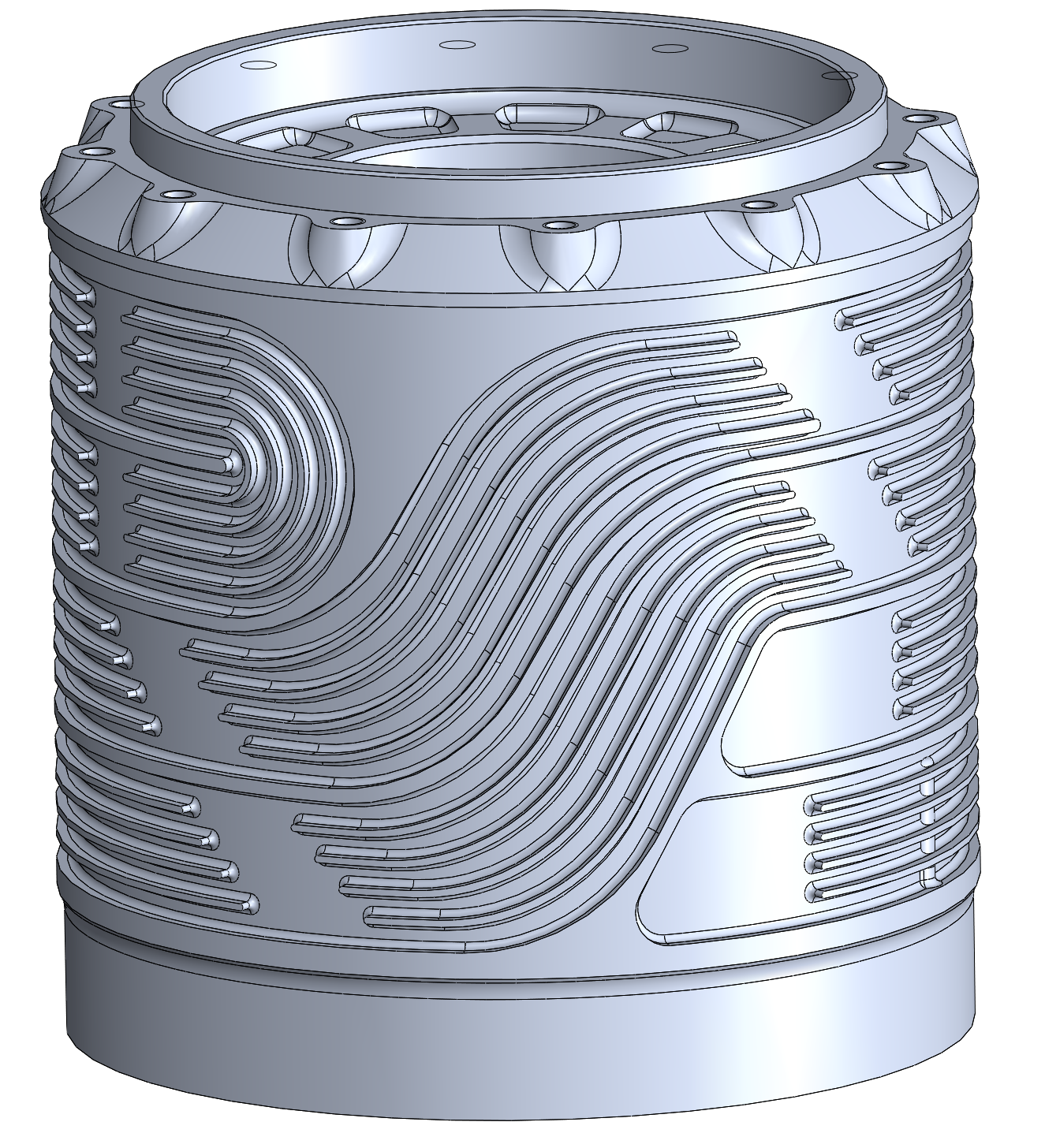
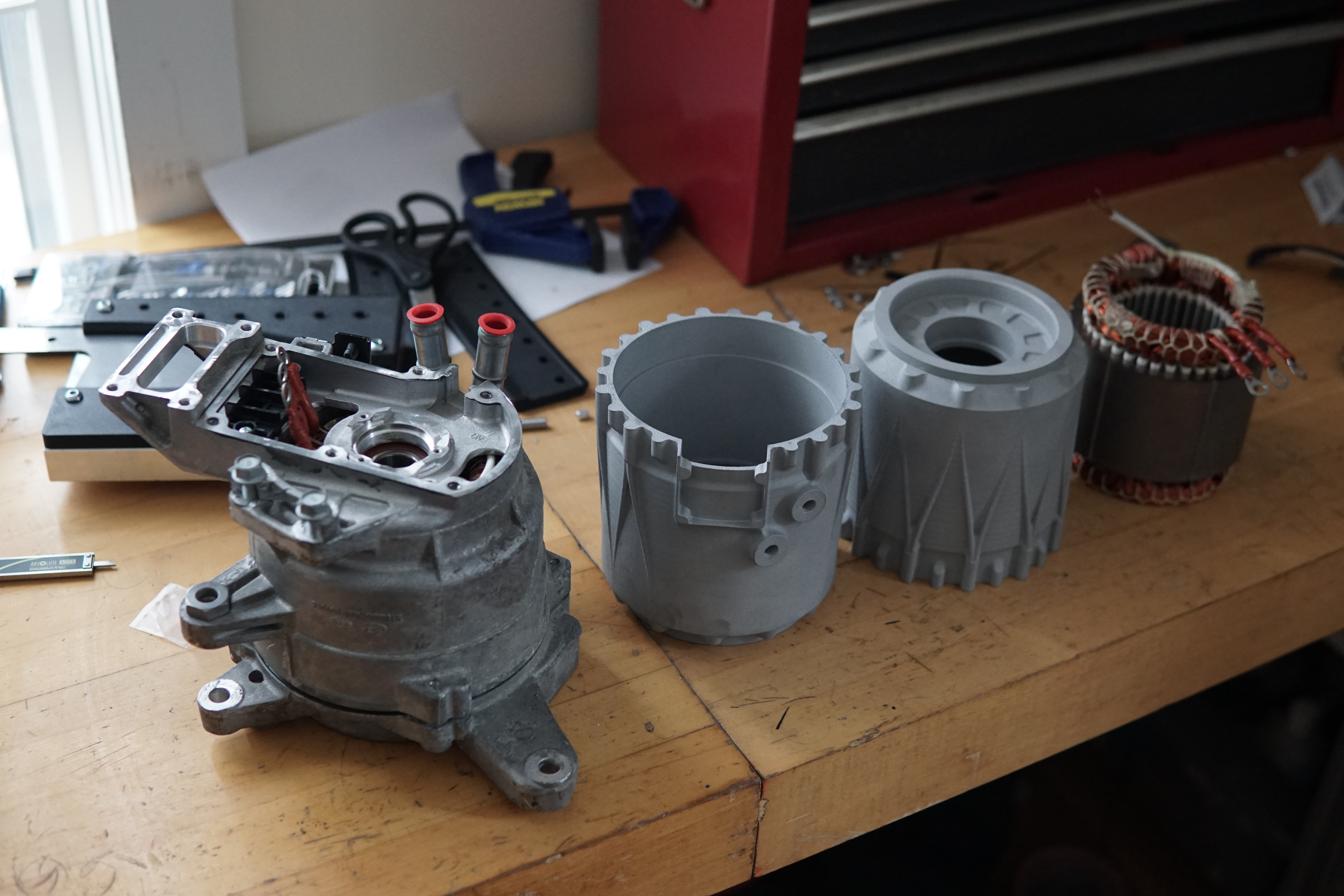
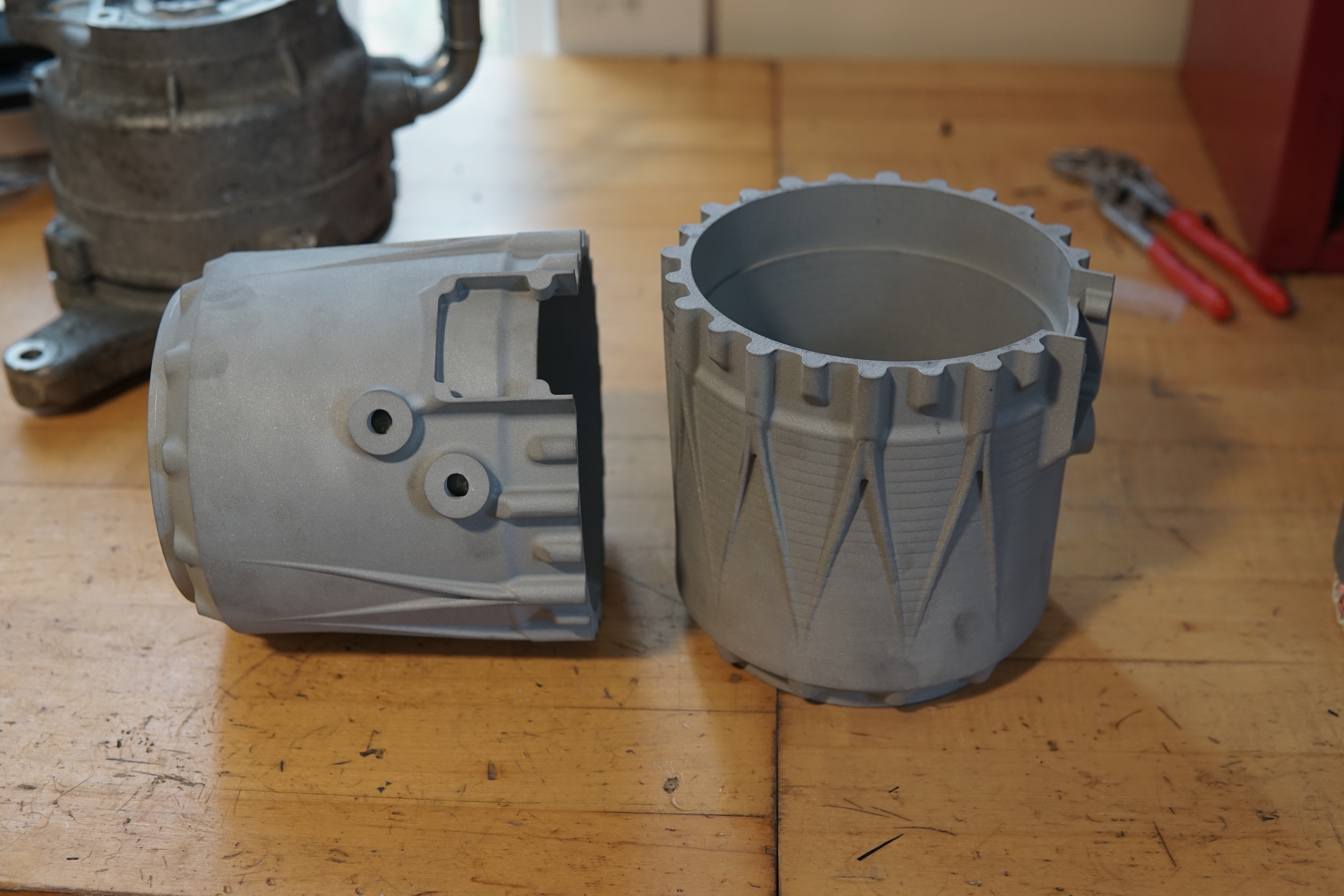
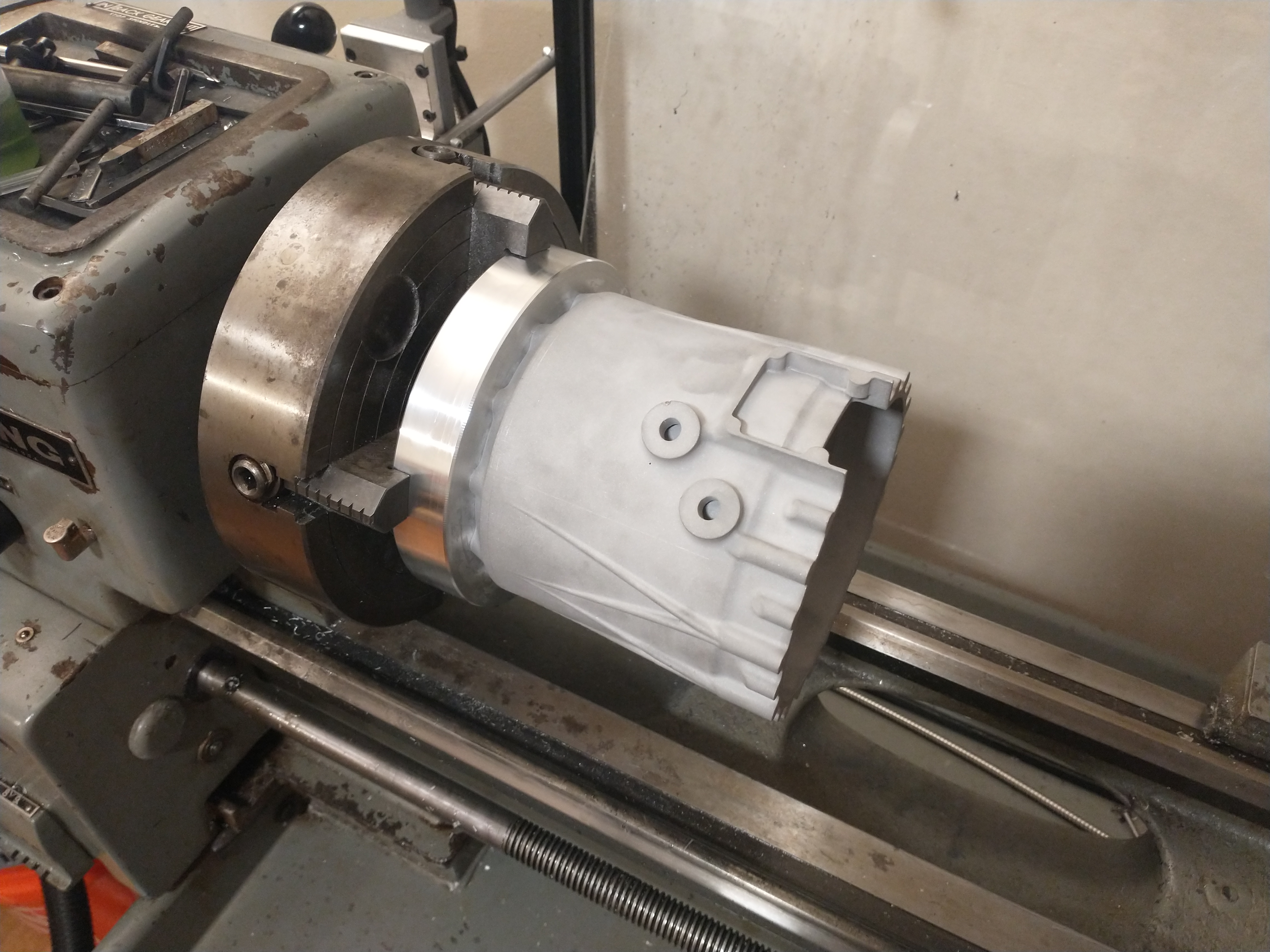
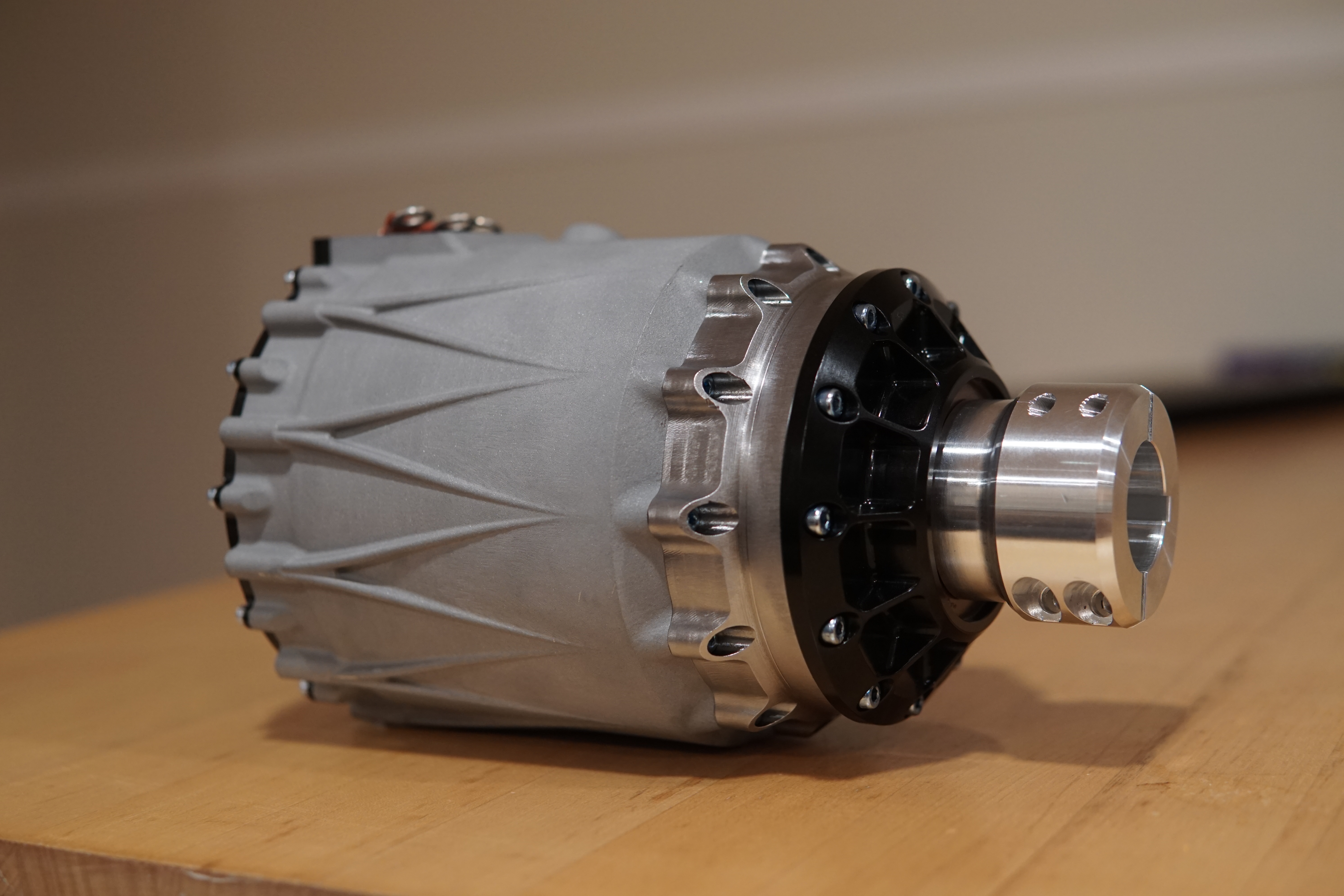
For re-housing the motors, I tried out PCBWay's aluminum 3d printing services. Printing the housing let me integrate a waterjacket into a monolithic housing, and was cheaper than getting the housings machined from multiple parts out of billet.
For the waterjacket I did a counterflow design, mostly for mechanical reasons so the inlet and outlet would be right next to each other. I added ribs down the water channels to add surface area and reduce the pressure drop around the 180 bend (top left in the picture below). Not that I actually did any heat exchanger math or CFD to back up this design. If the stock waterjacket was adequate this should be good enough....
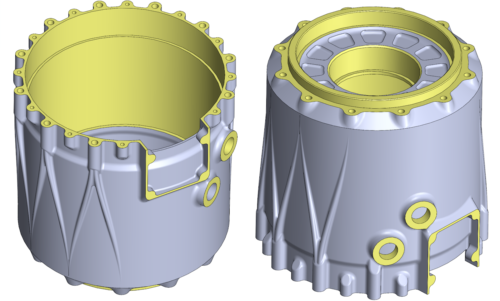
The yellow surfaces on the model below were post-machined. These all had 1.5mm-2mm extra material added for machining away
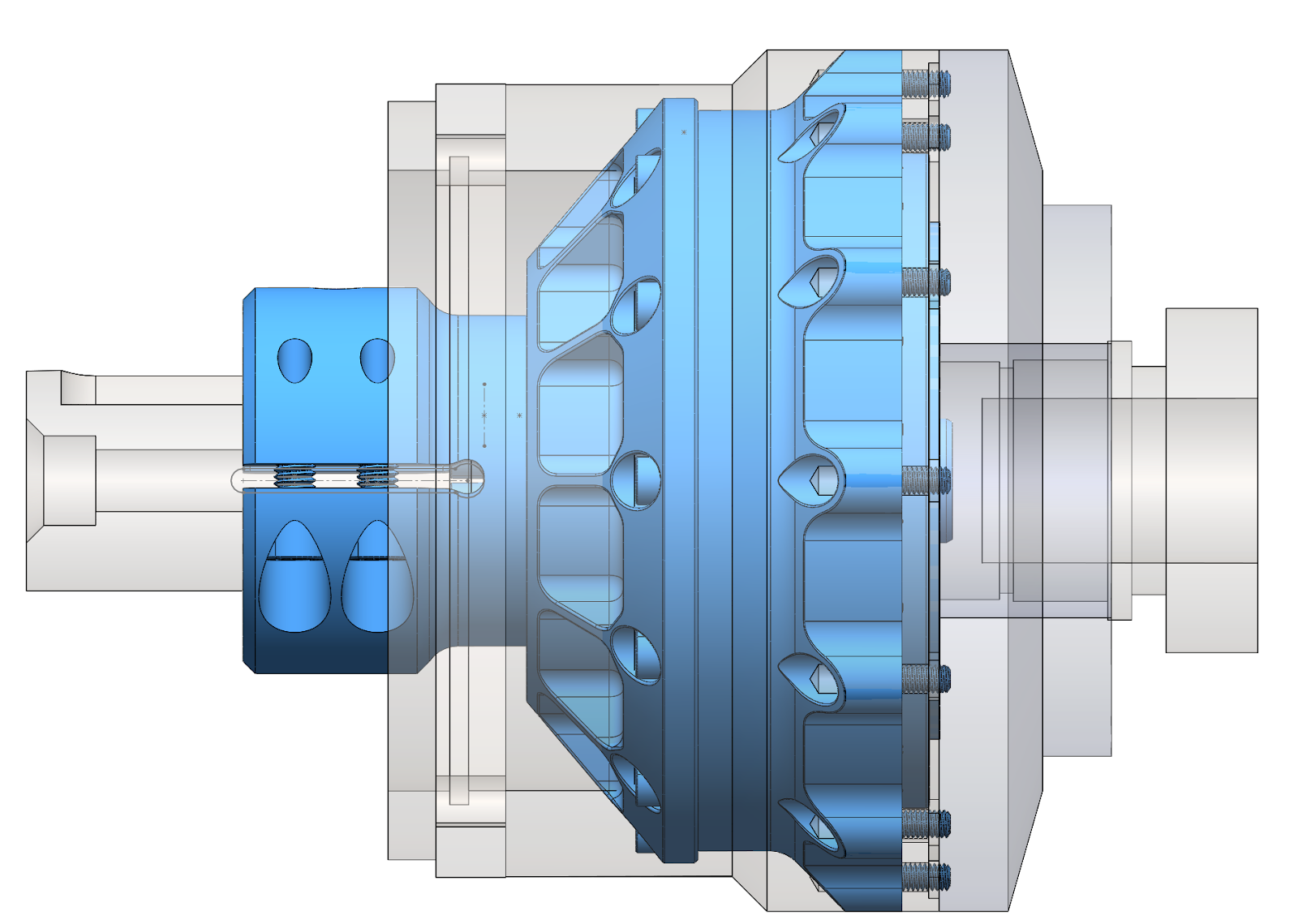
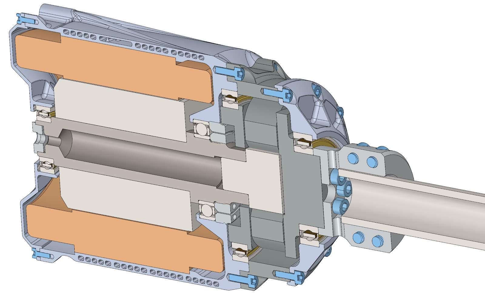
Cross section of the full drive unit:
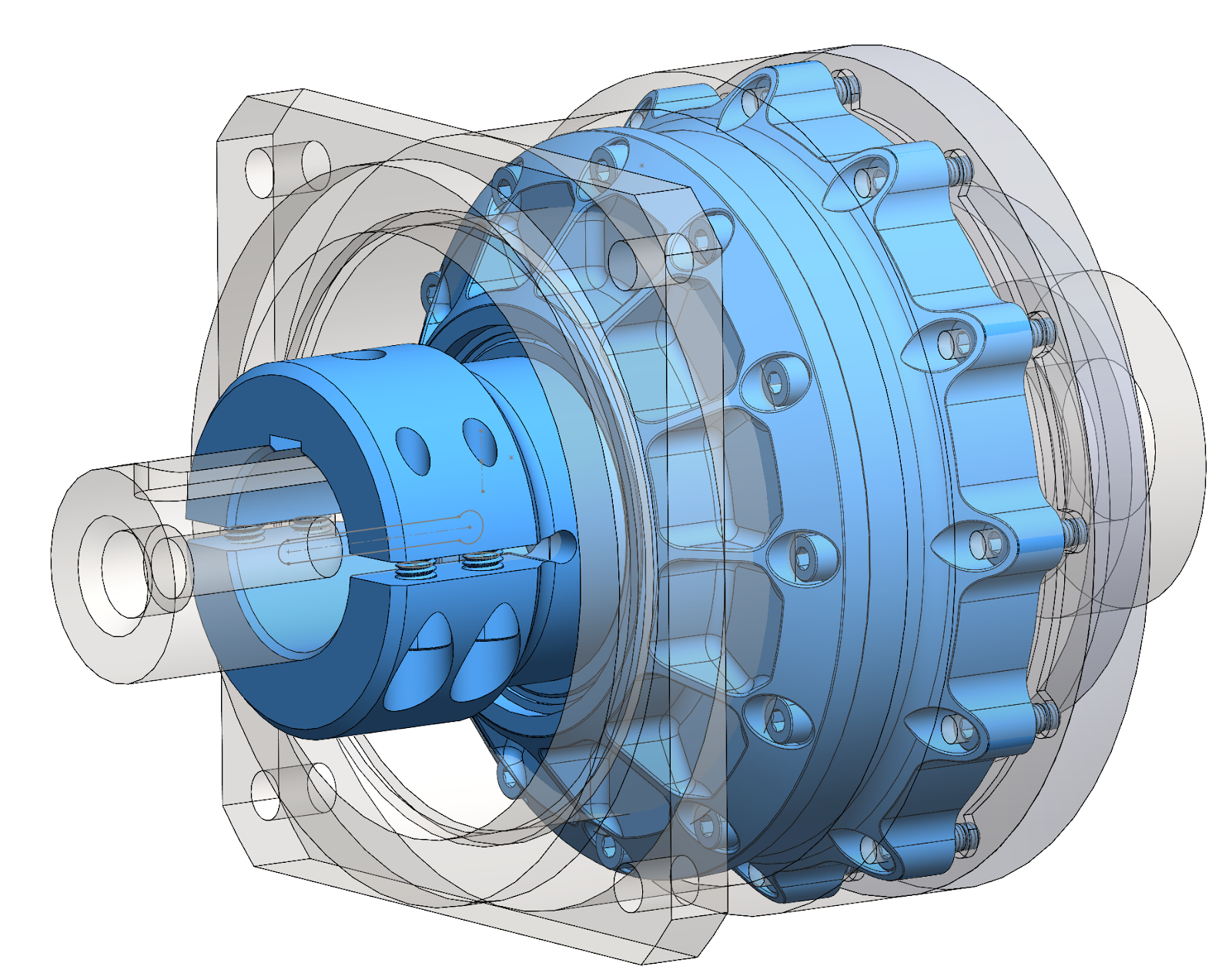
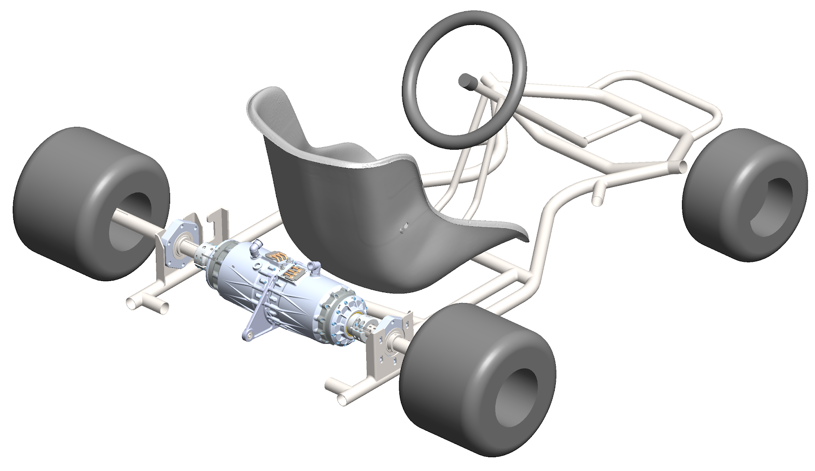
In context on the kart:
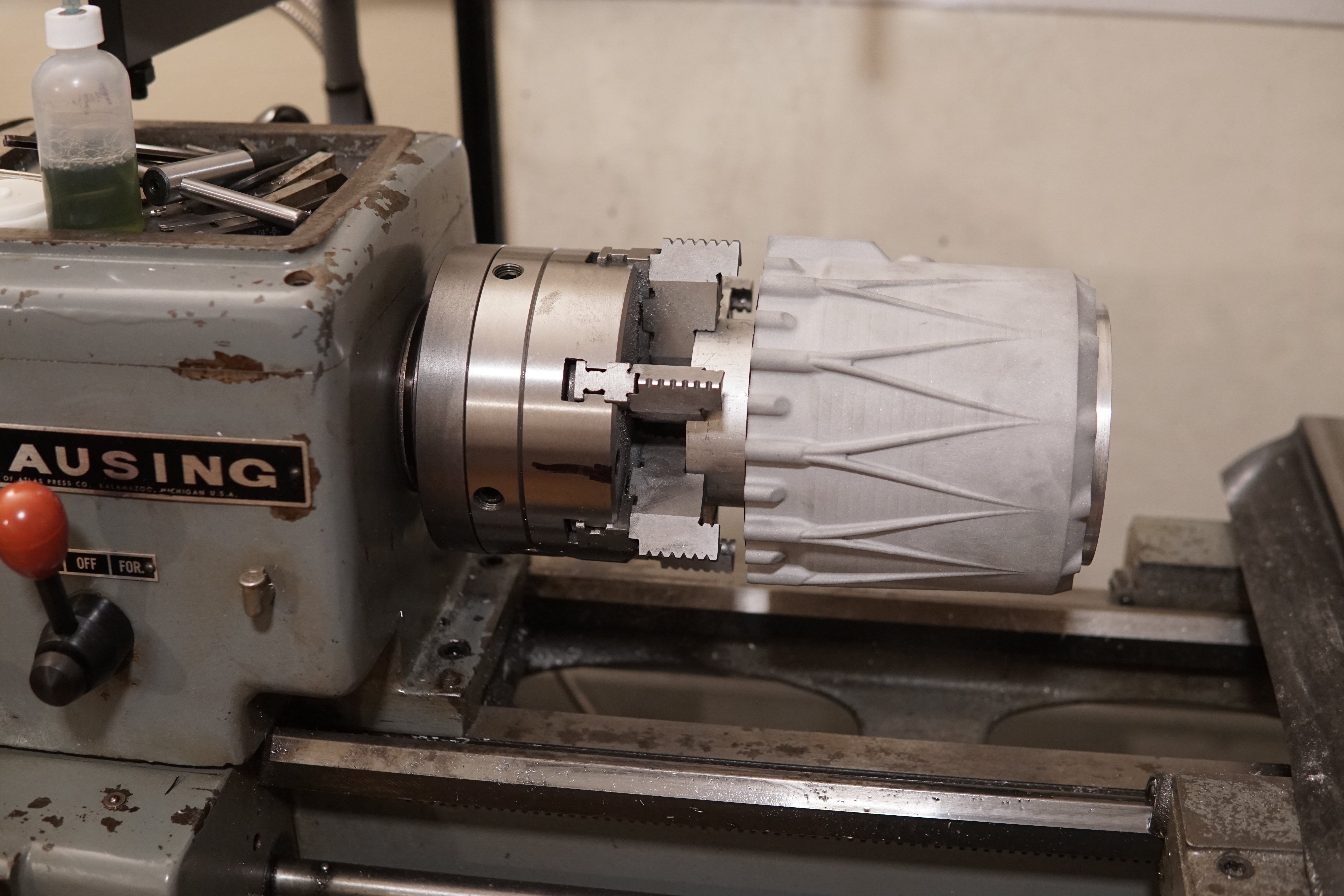
The PCBWay printed housings turned out great - they must have done a ton of hand finishing work, there were no traces of support material left on the build platform side of the part. They were designed to be printed motor bore up, so all the circular features were in the print plane and ended up very concentric and close to nominal size.
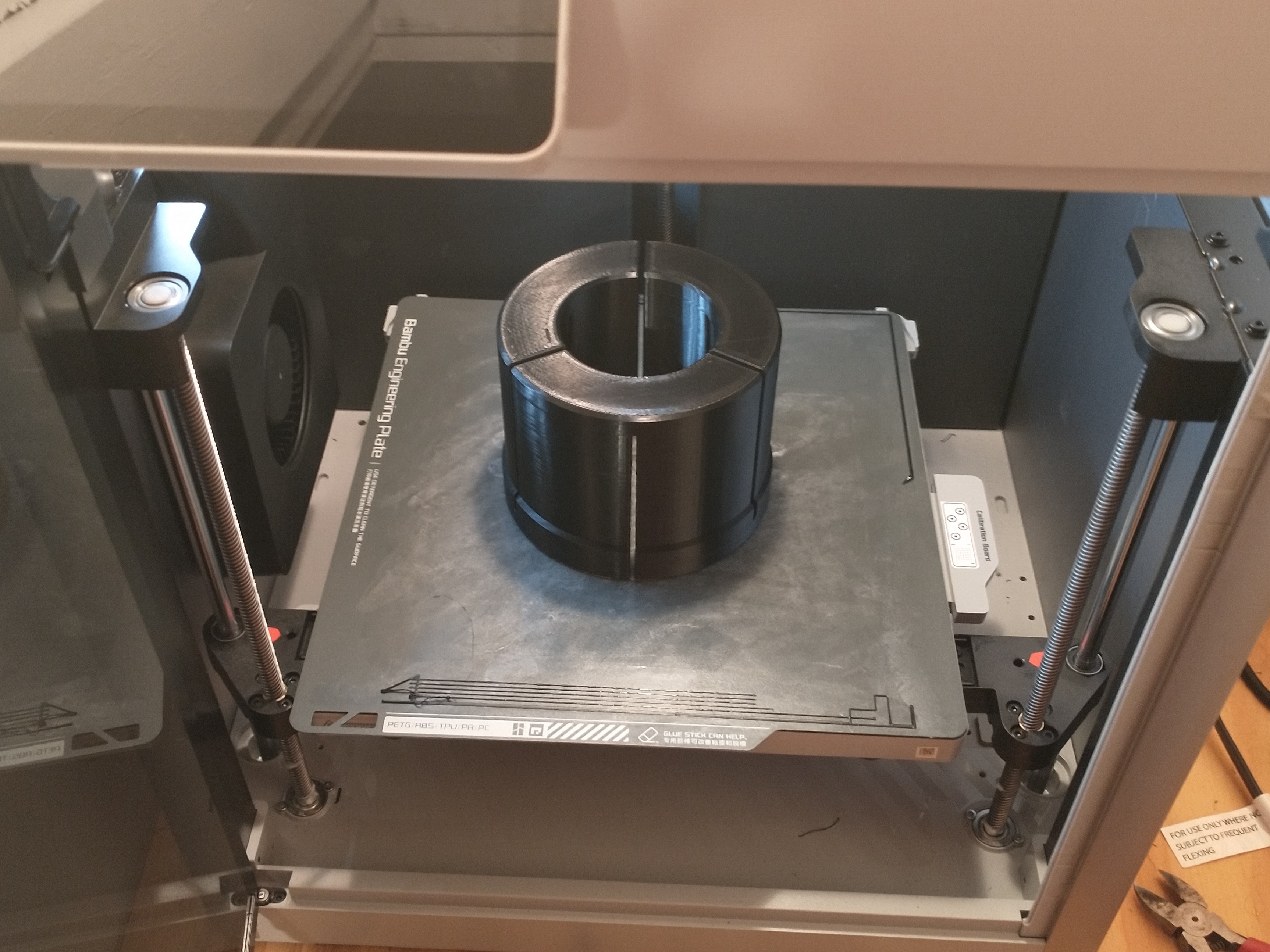
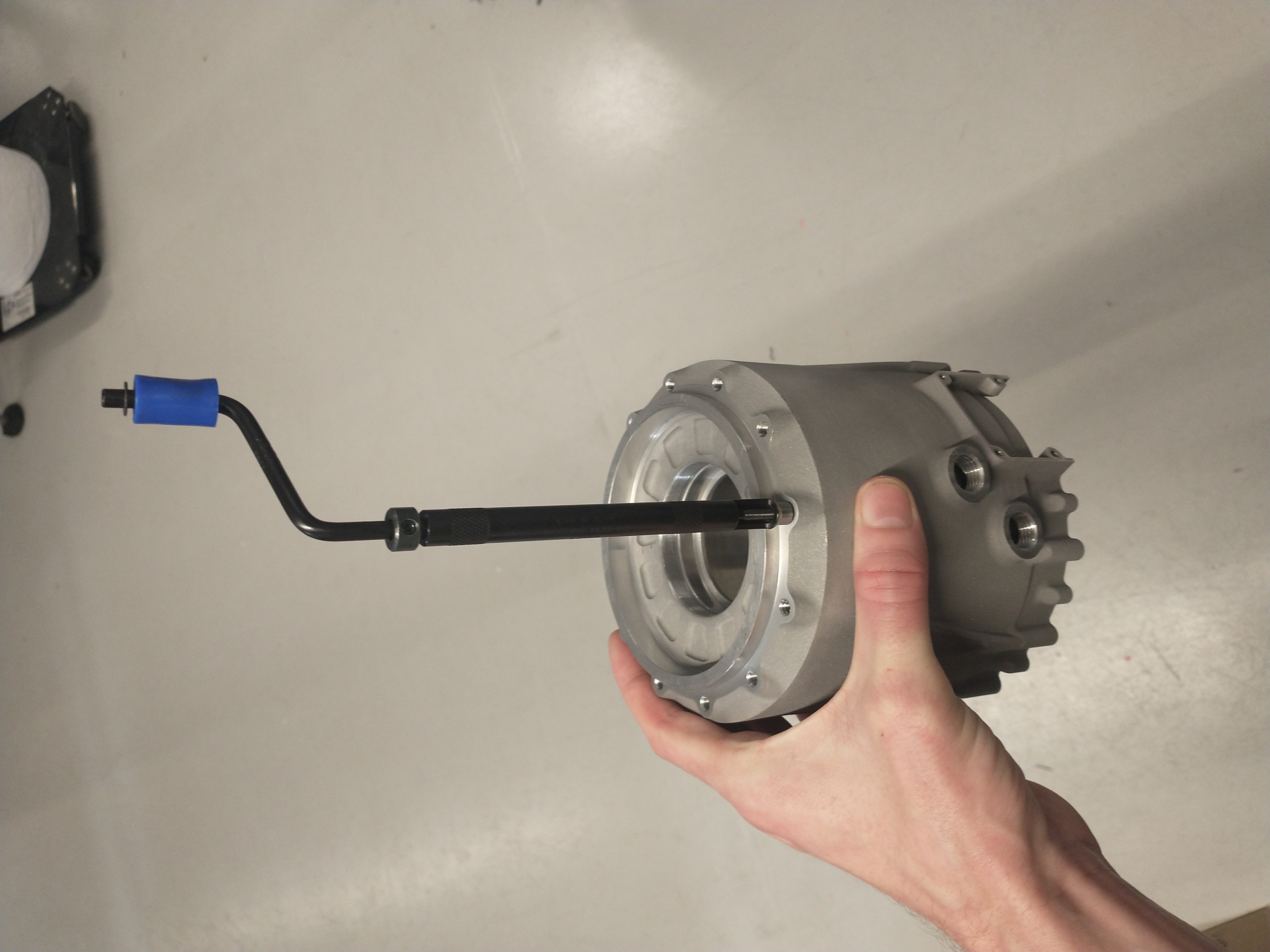
 |
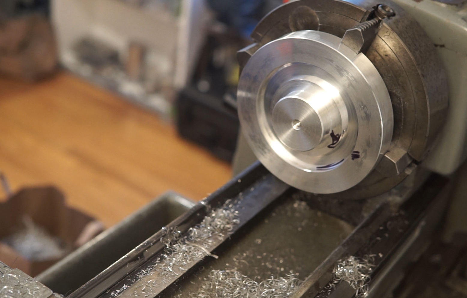
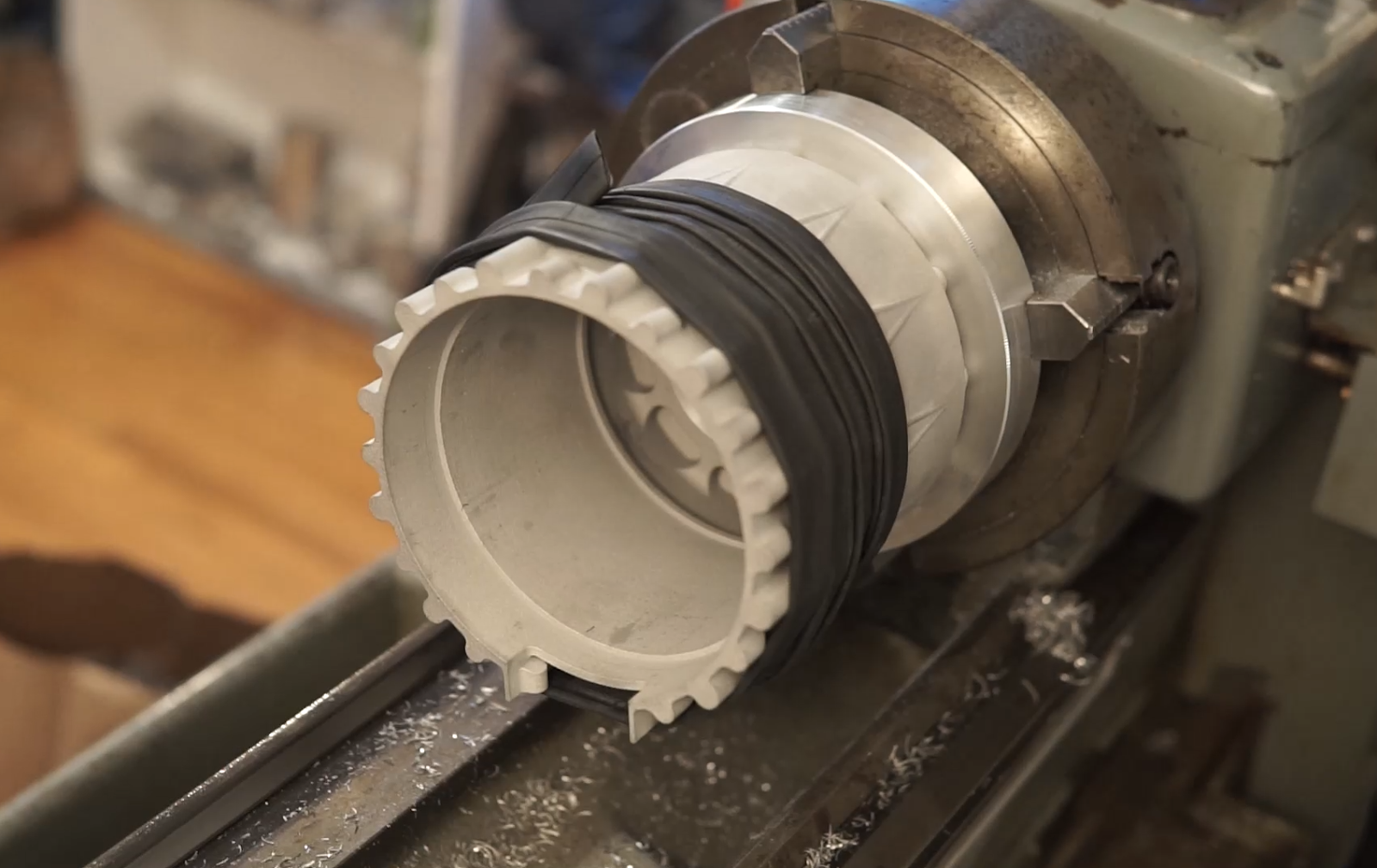
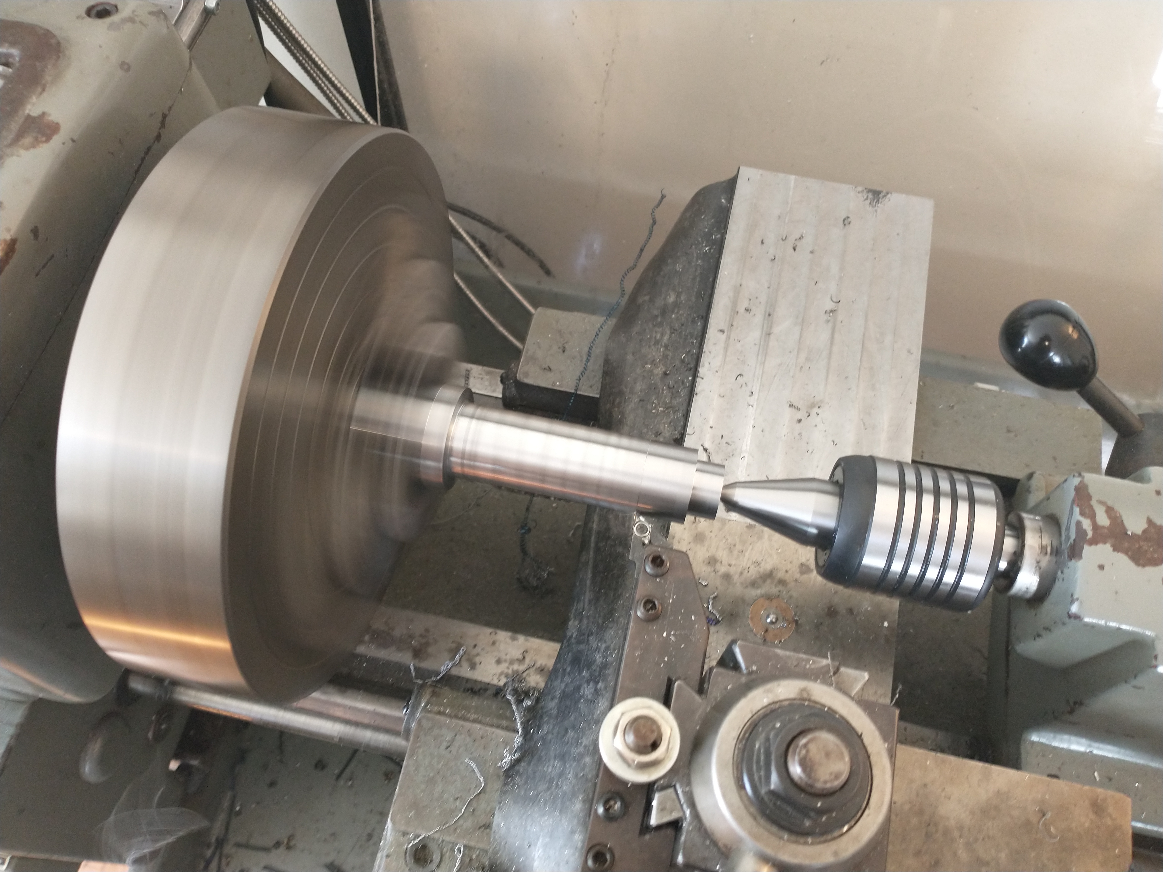
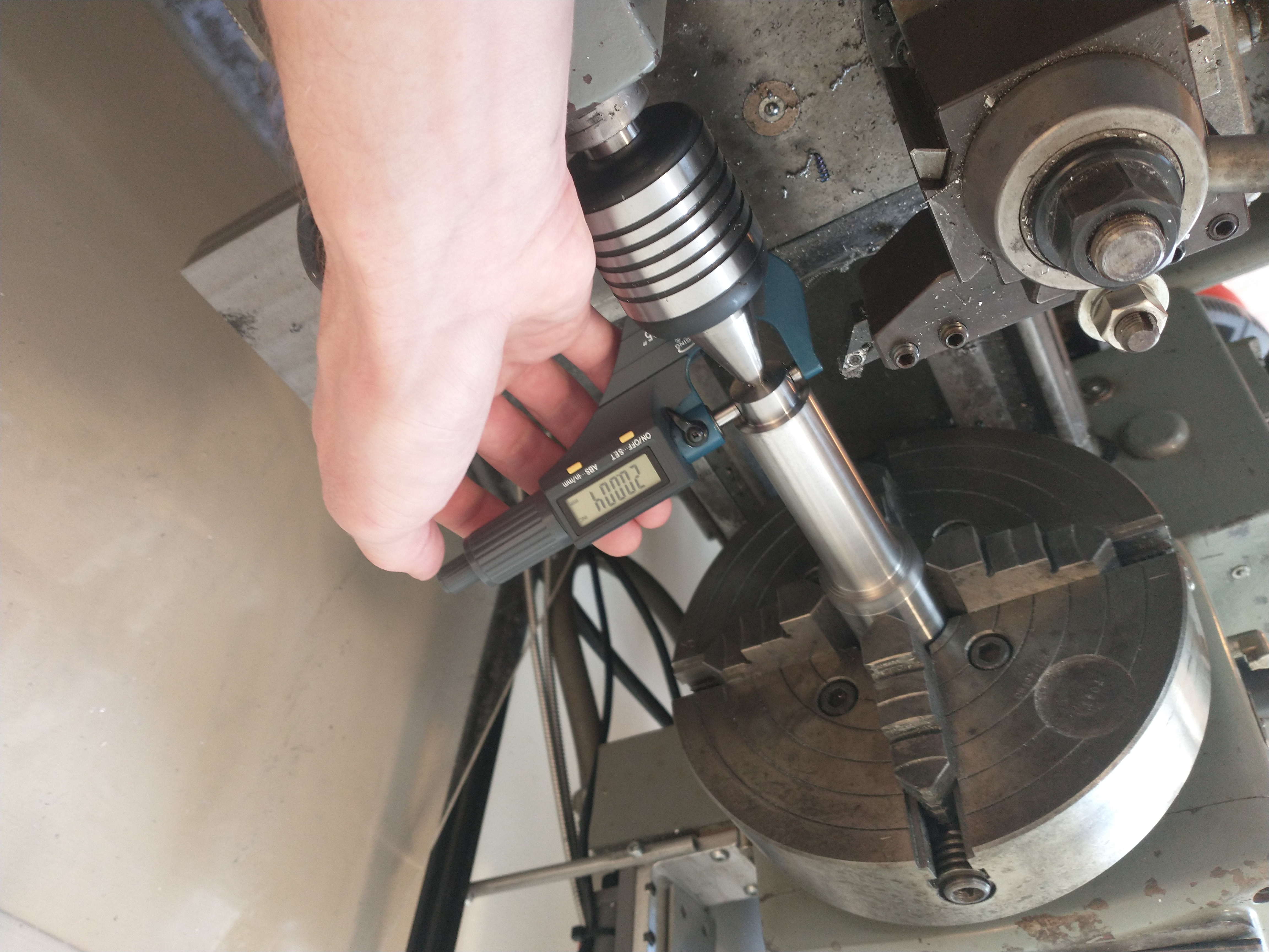
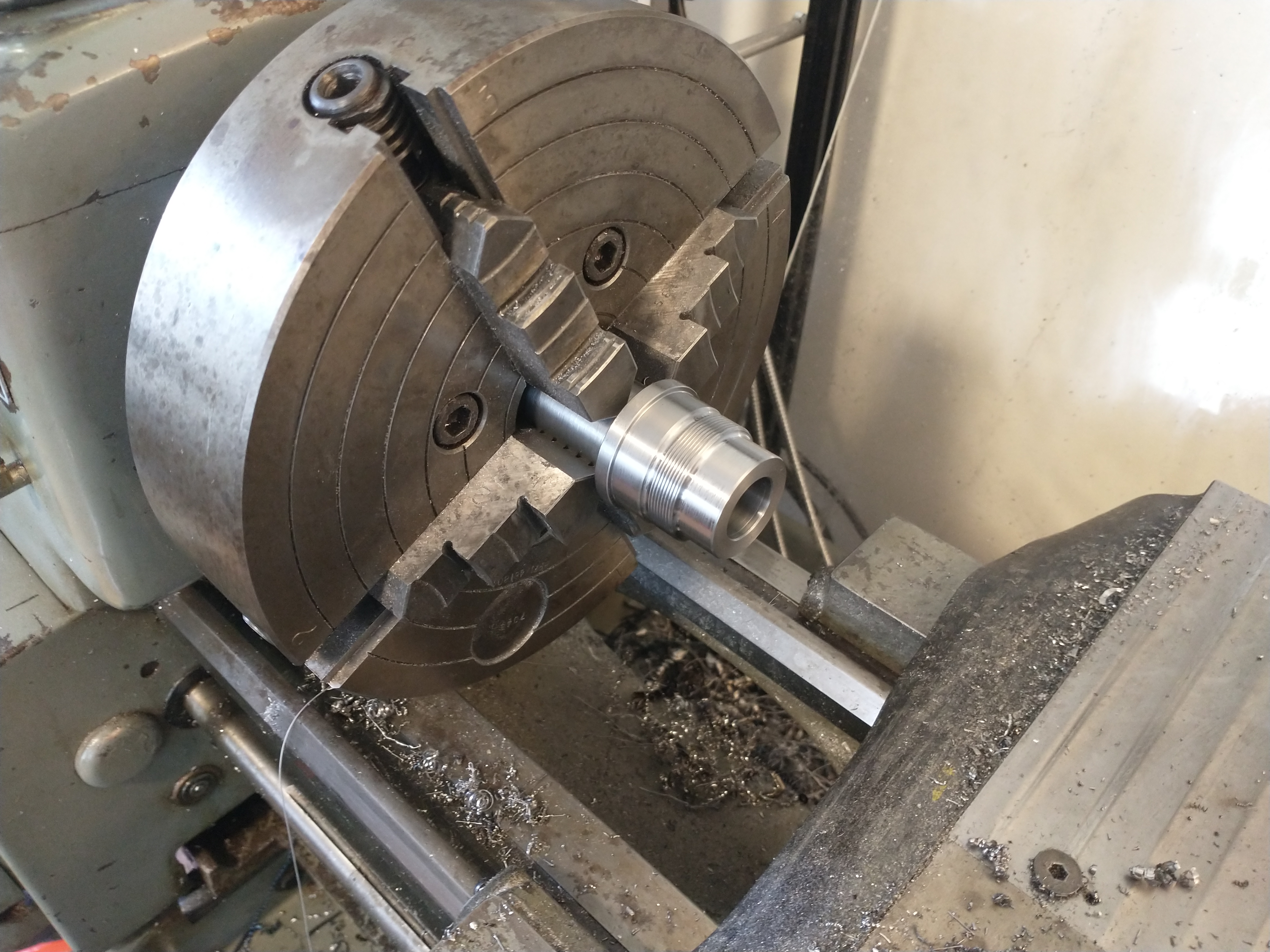
| The tapered shaft part of the fixture |
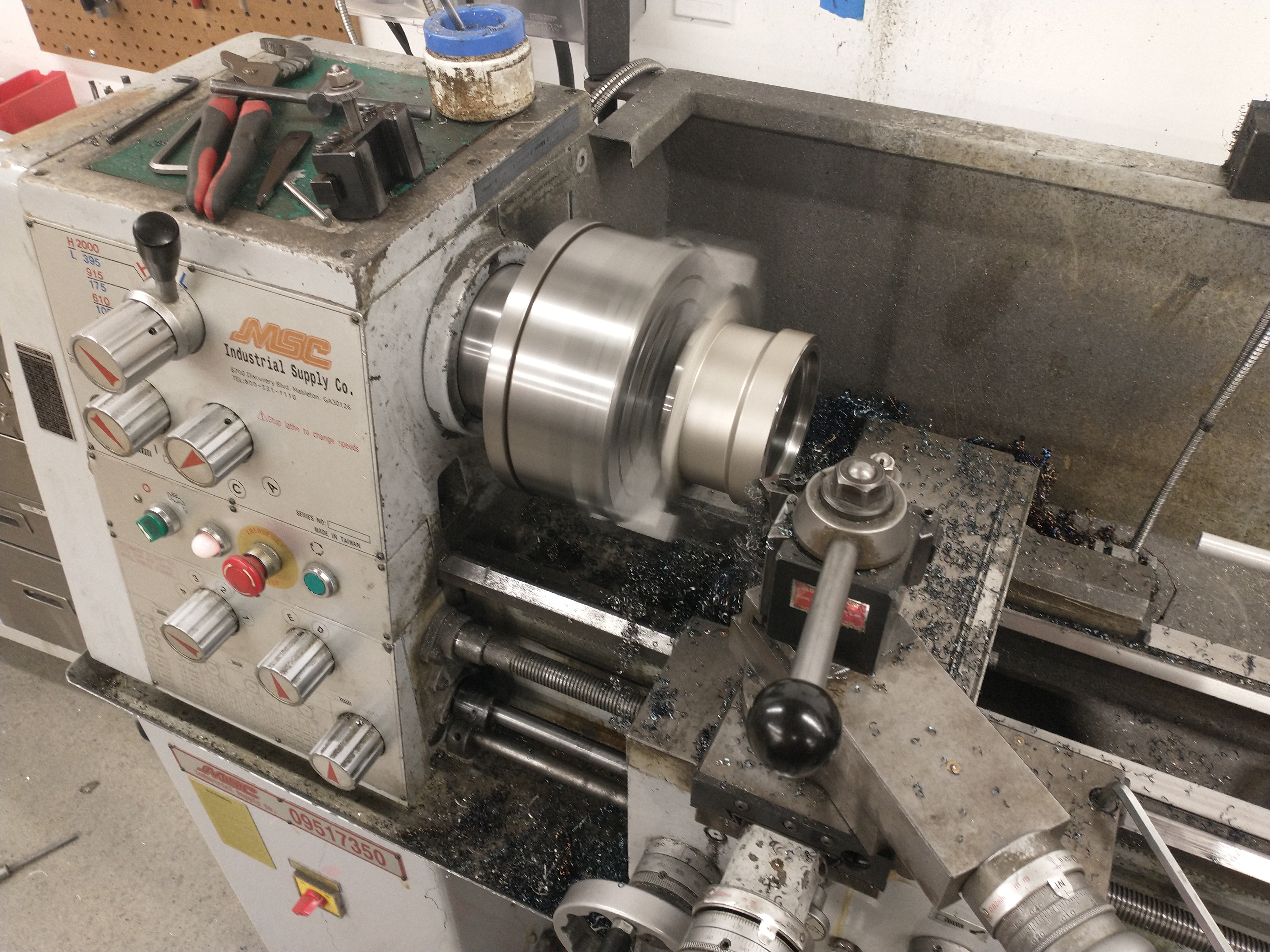
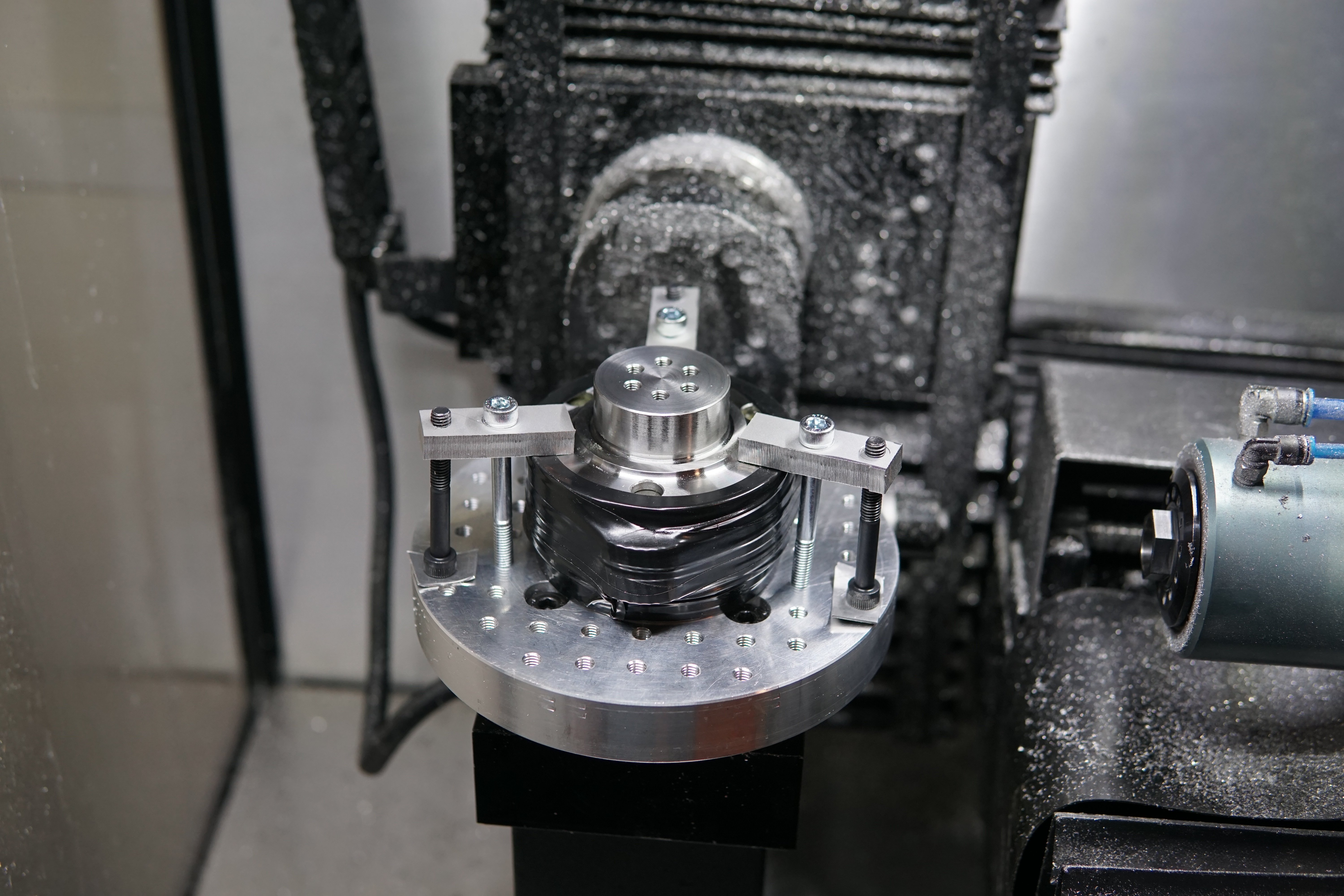
To get the fixture to run true I skimmed the outside in-place on the lathe. A single M8 bolt and a big aluminum washer clamp the mandrel axially to expand it.
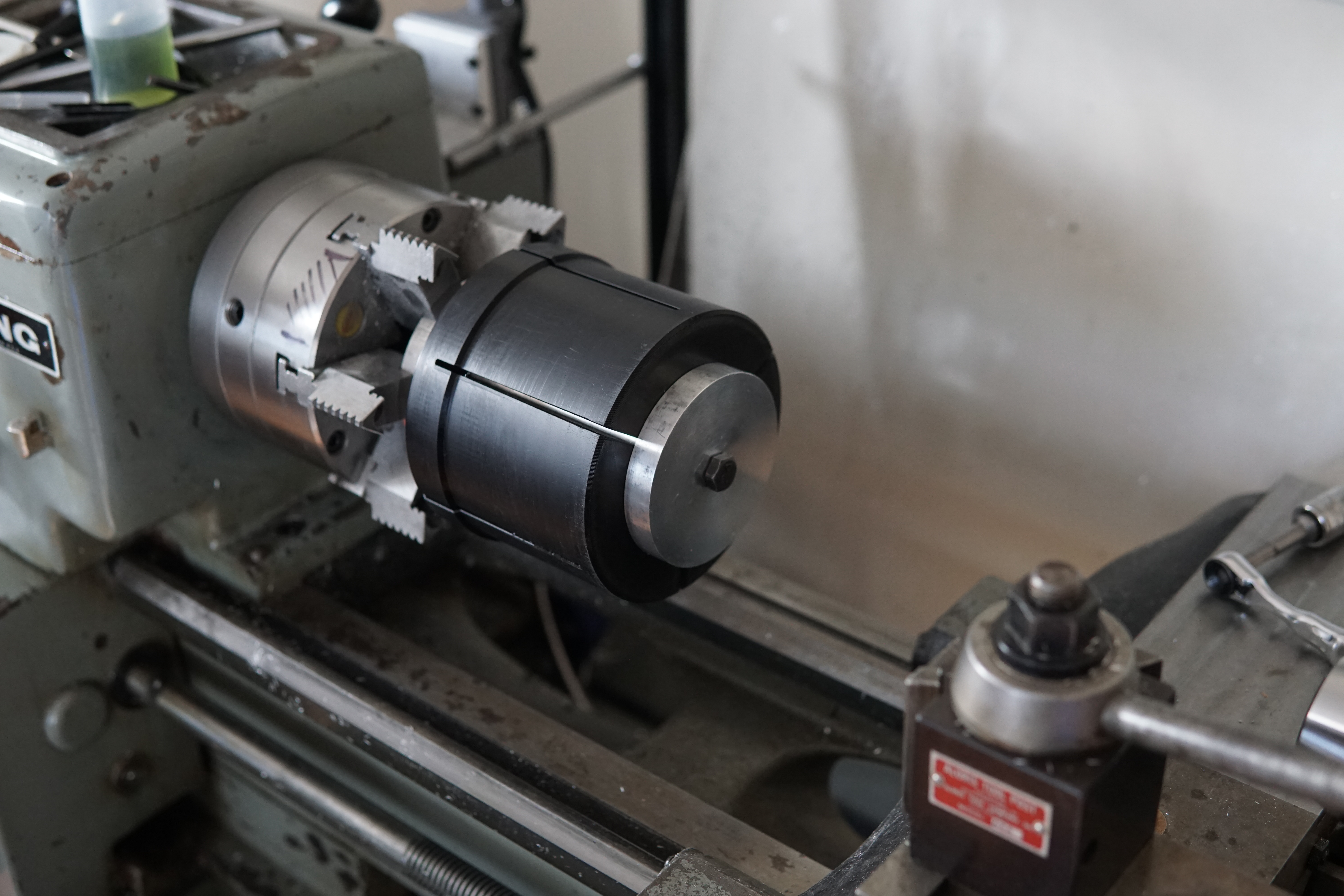
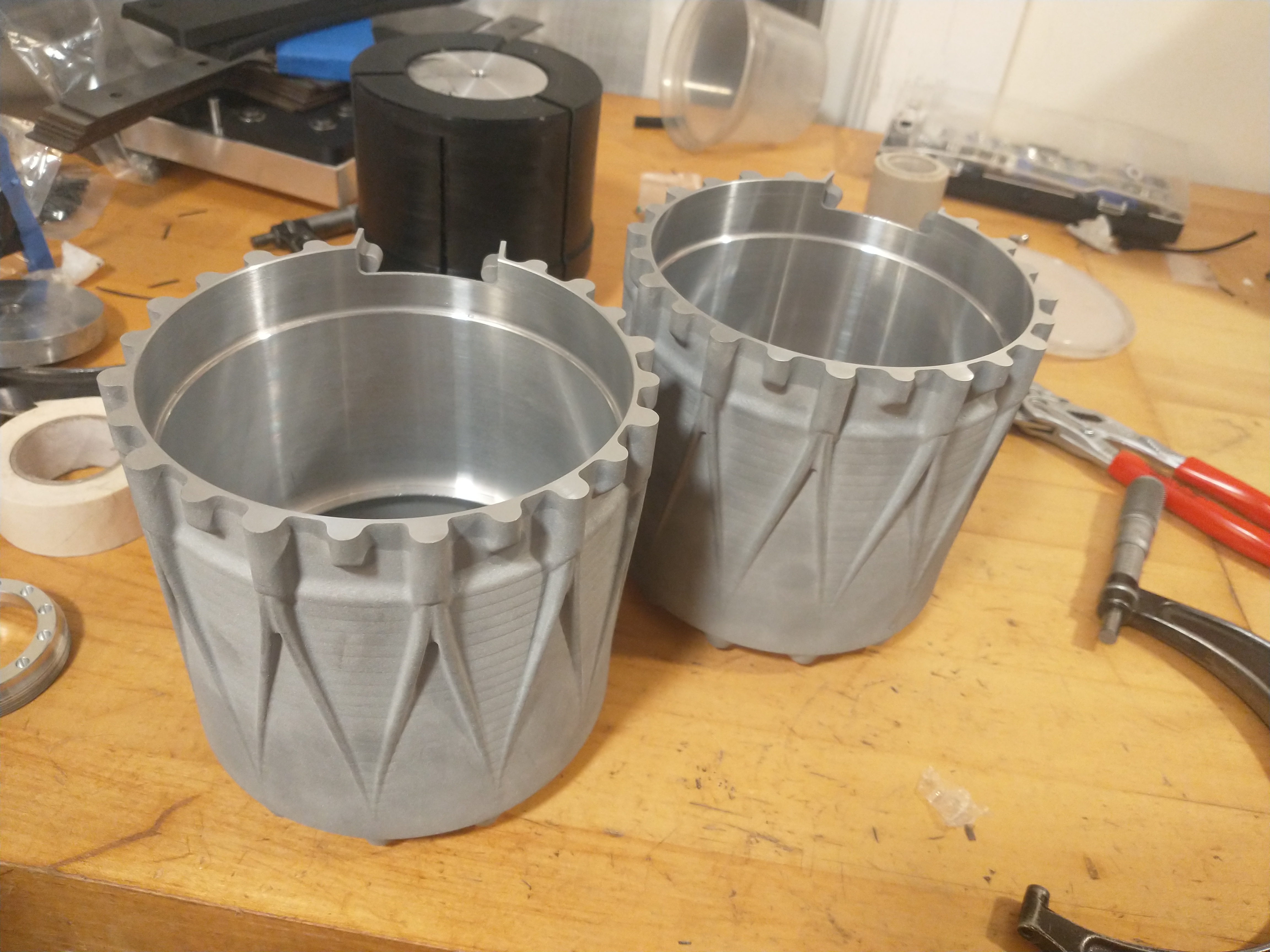
First operation finished on both parts:
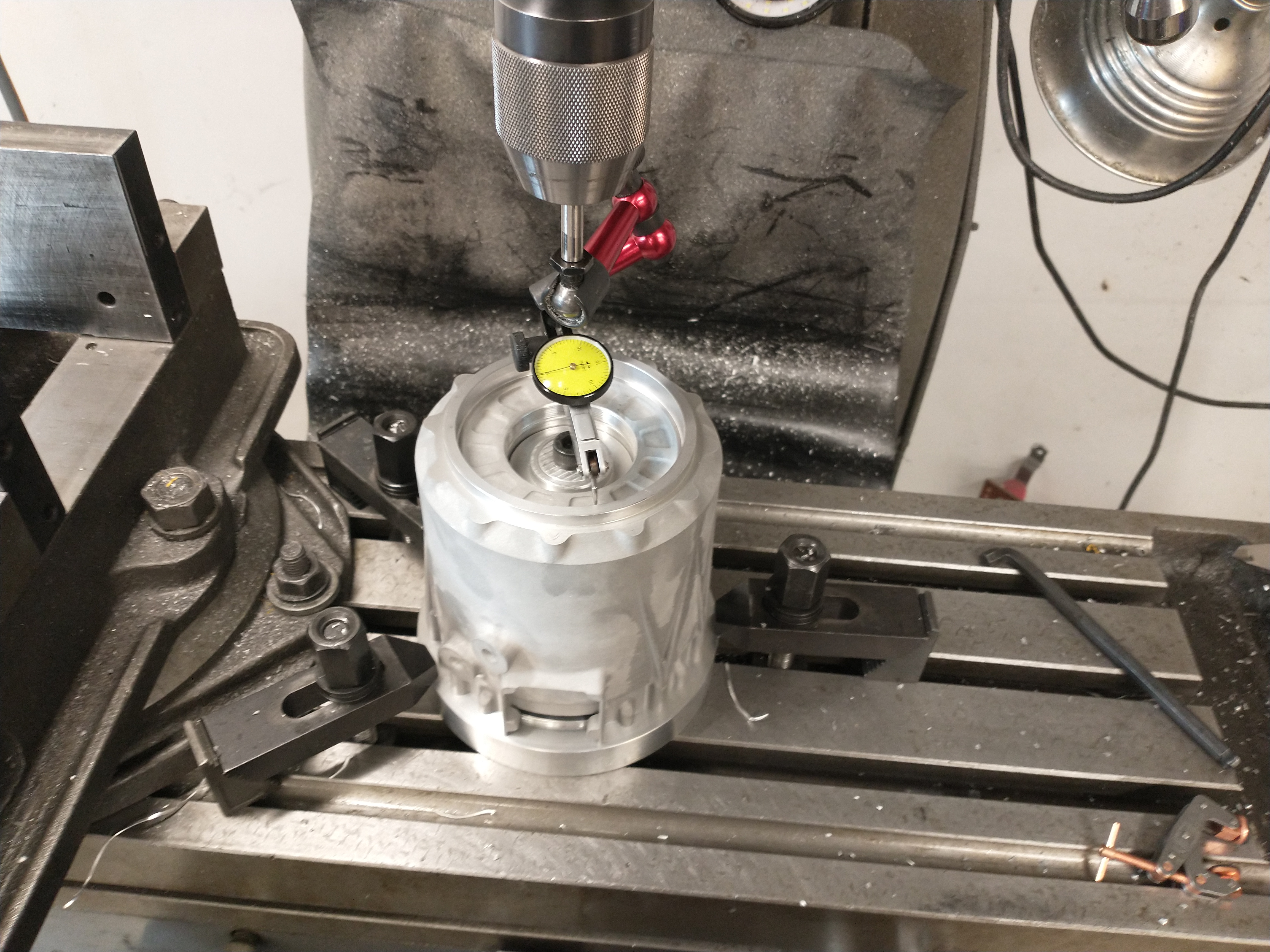
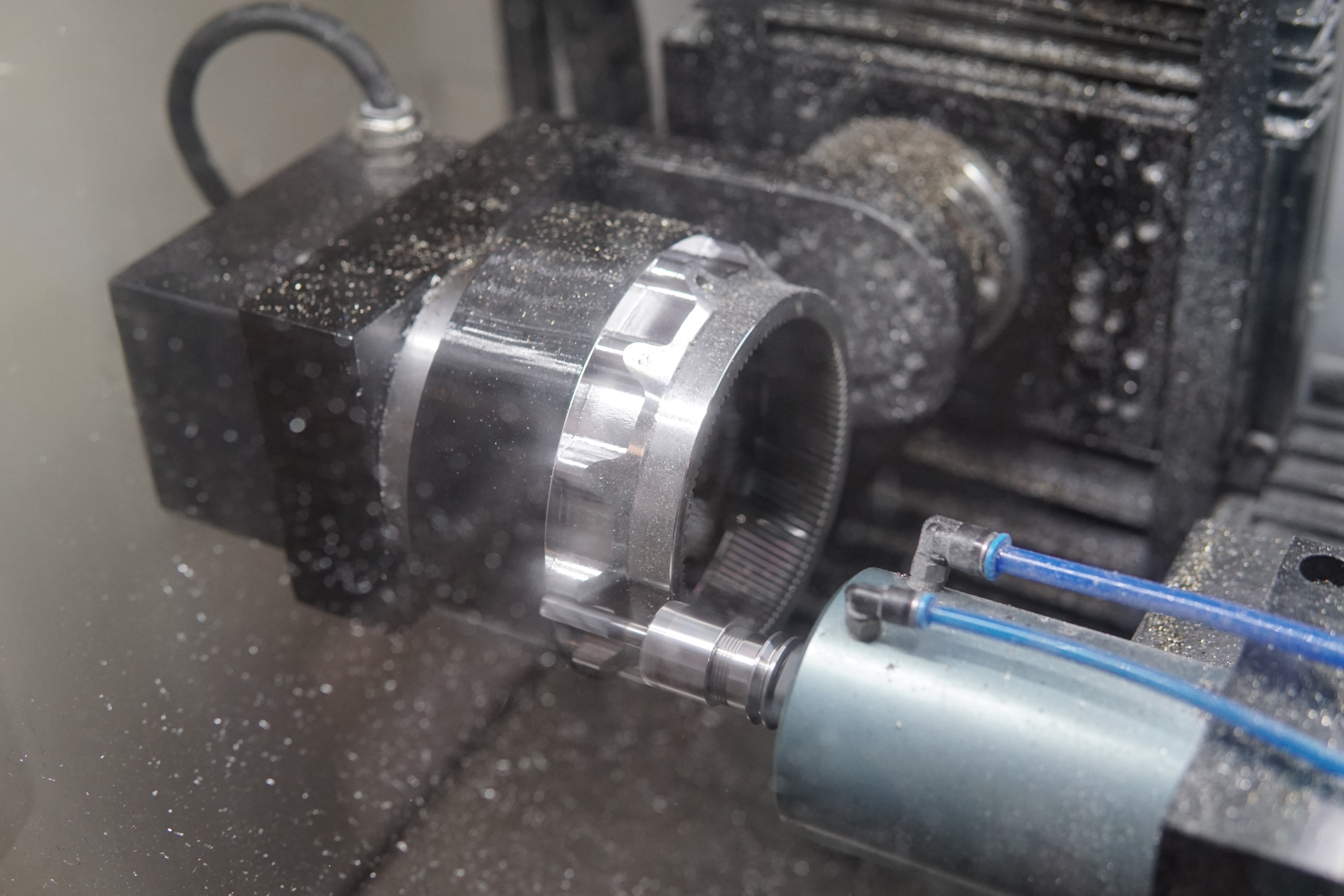
Runout on the as-printed motor bore after fixturing. After post-machining there would be some nominally 1 and 1.5mm thick walls, so I didn't have a ton of wiggle room:
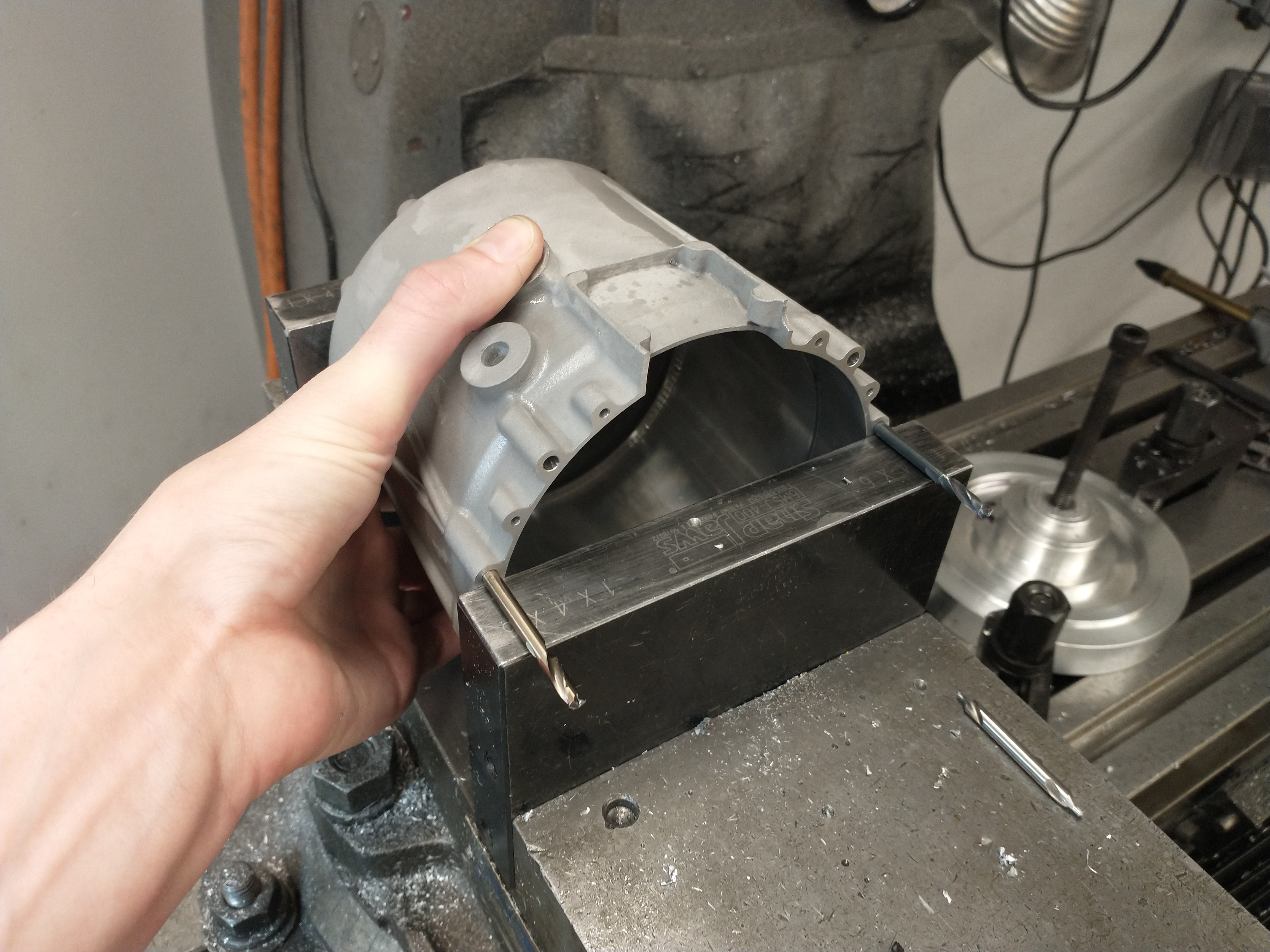
Large thin-walled parts like this are prone to ringing during machining. To damp out vibrations better I wrapped the housings in a bicycle inner tube - see video below of before/after ringing.
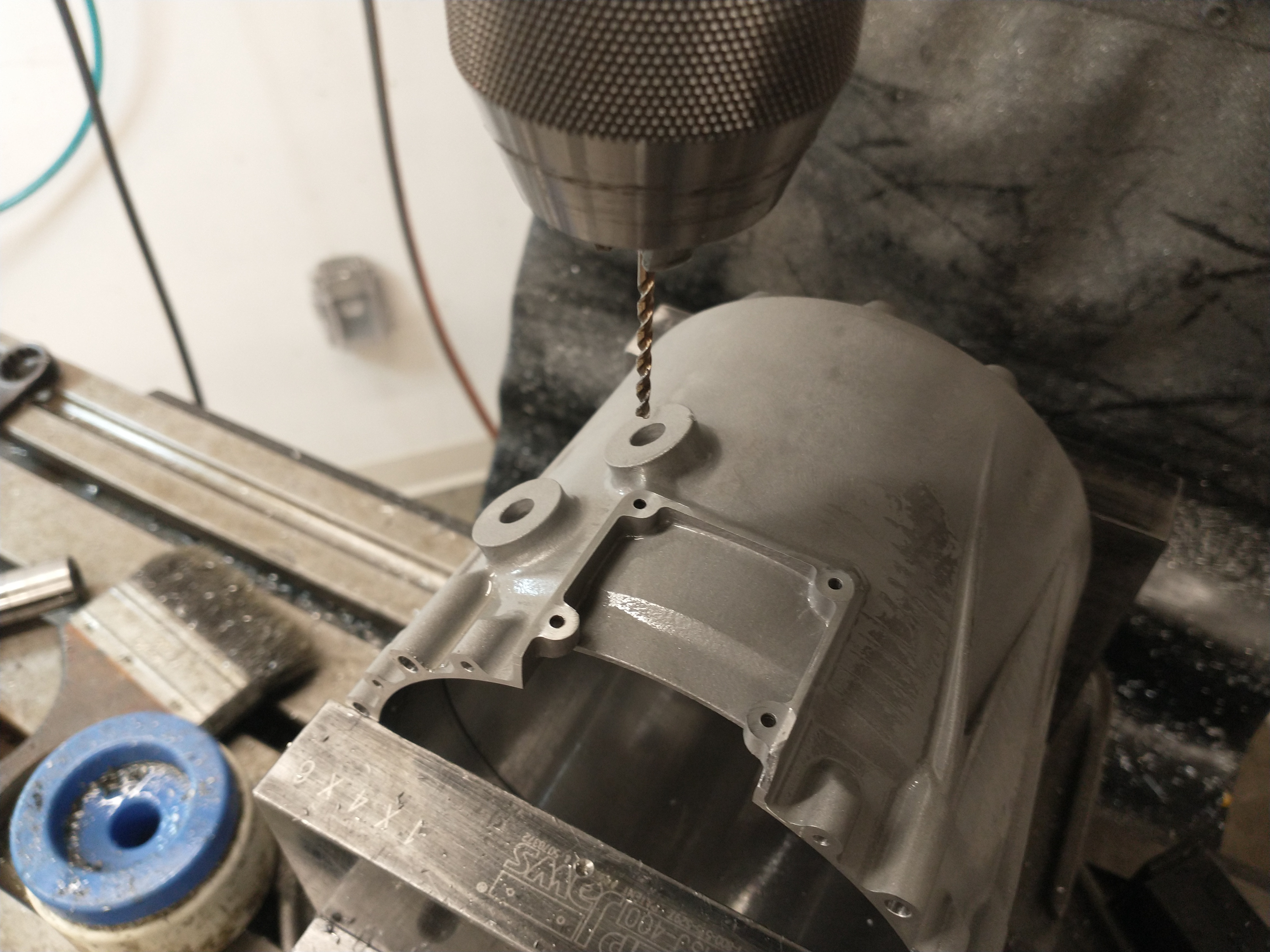
The milling was pretty simple - nothing tight tolerance, just a bunch of tapped holes and a few faces milled flat. I set up the housings on the Bridgeport using the same fixture as the previous turning step:
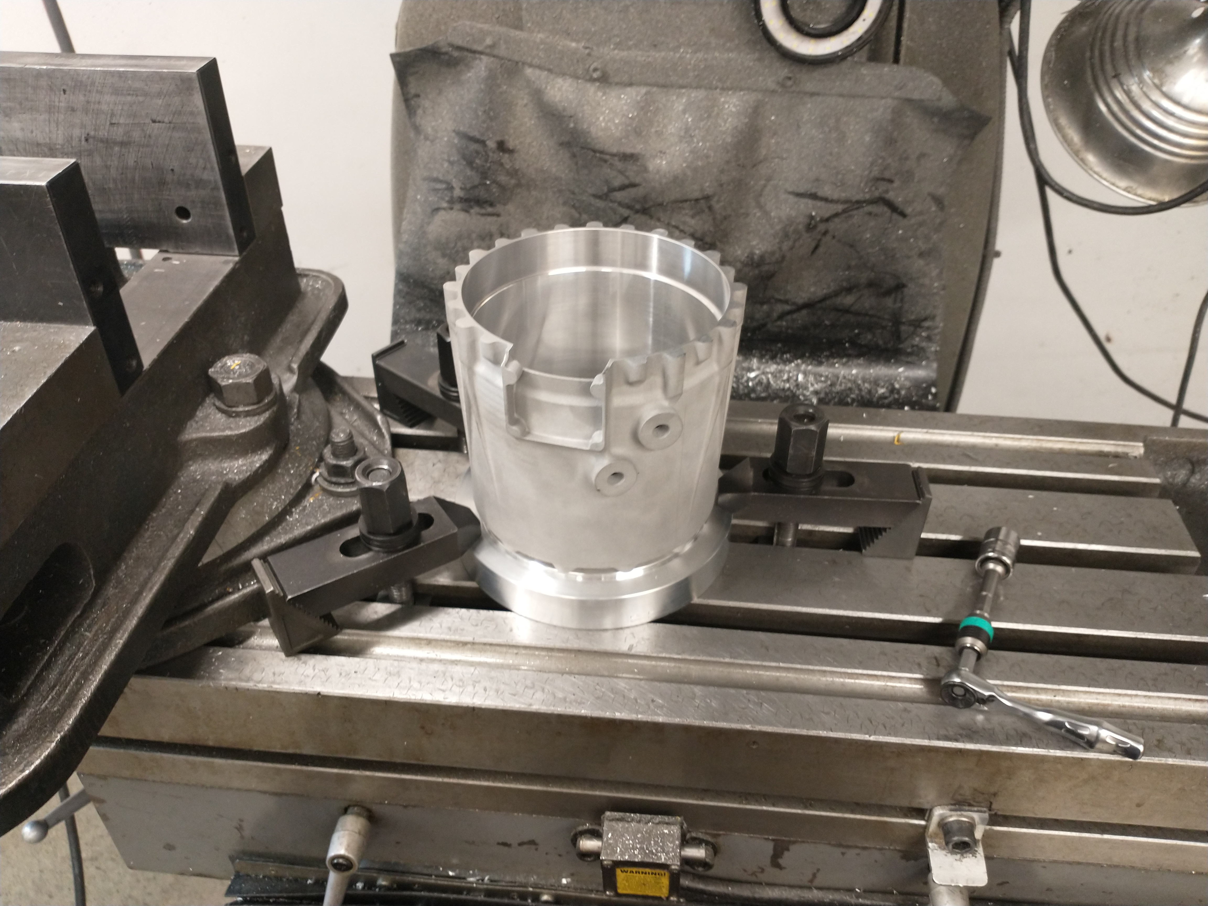
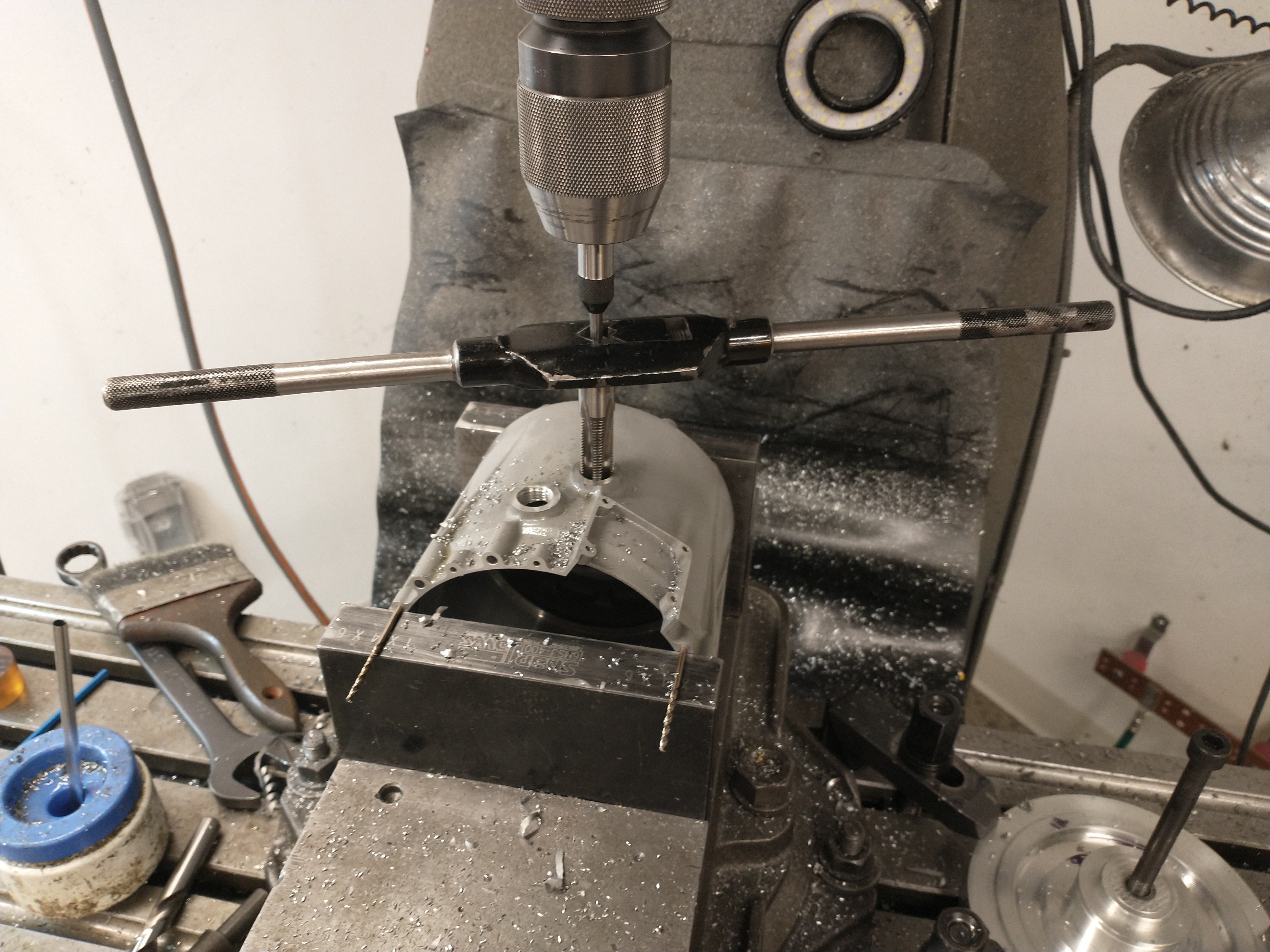
I preemptively helicoiled all the structural M4 threads on the part - the printed aluminum alloy (AlSi10Mg) is similar strength to 6061, so not particularly strong.
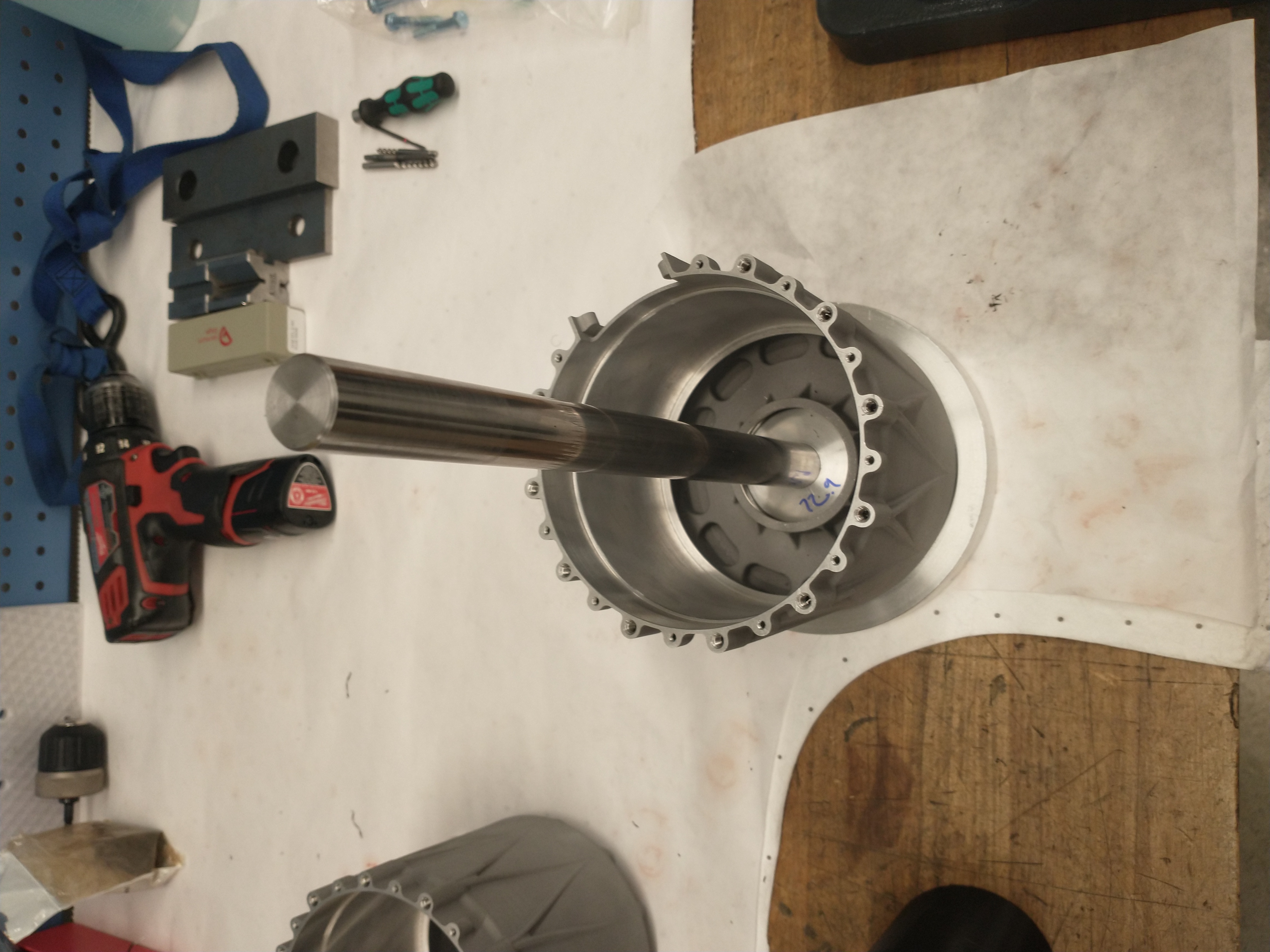
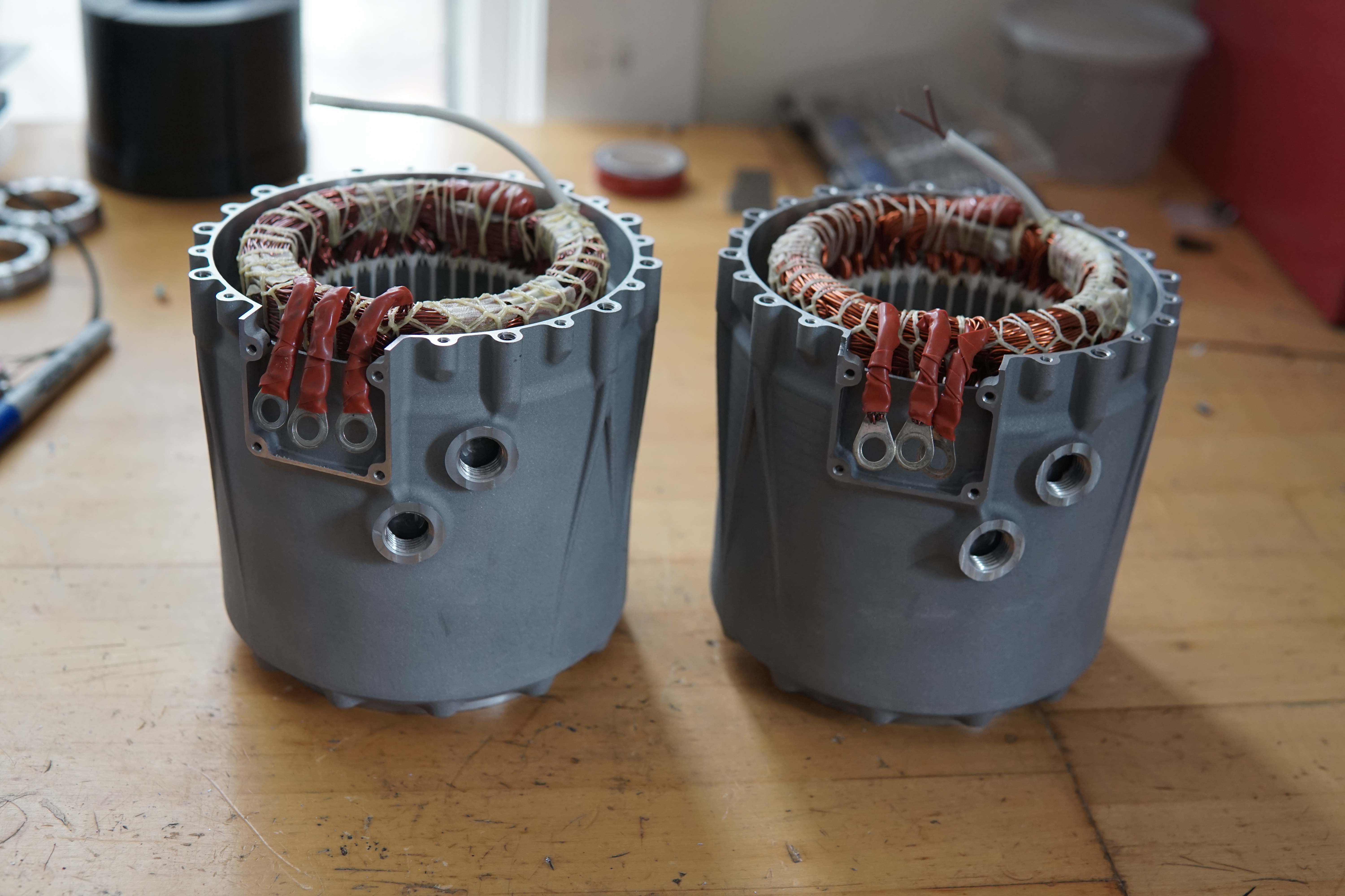
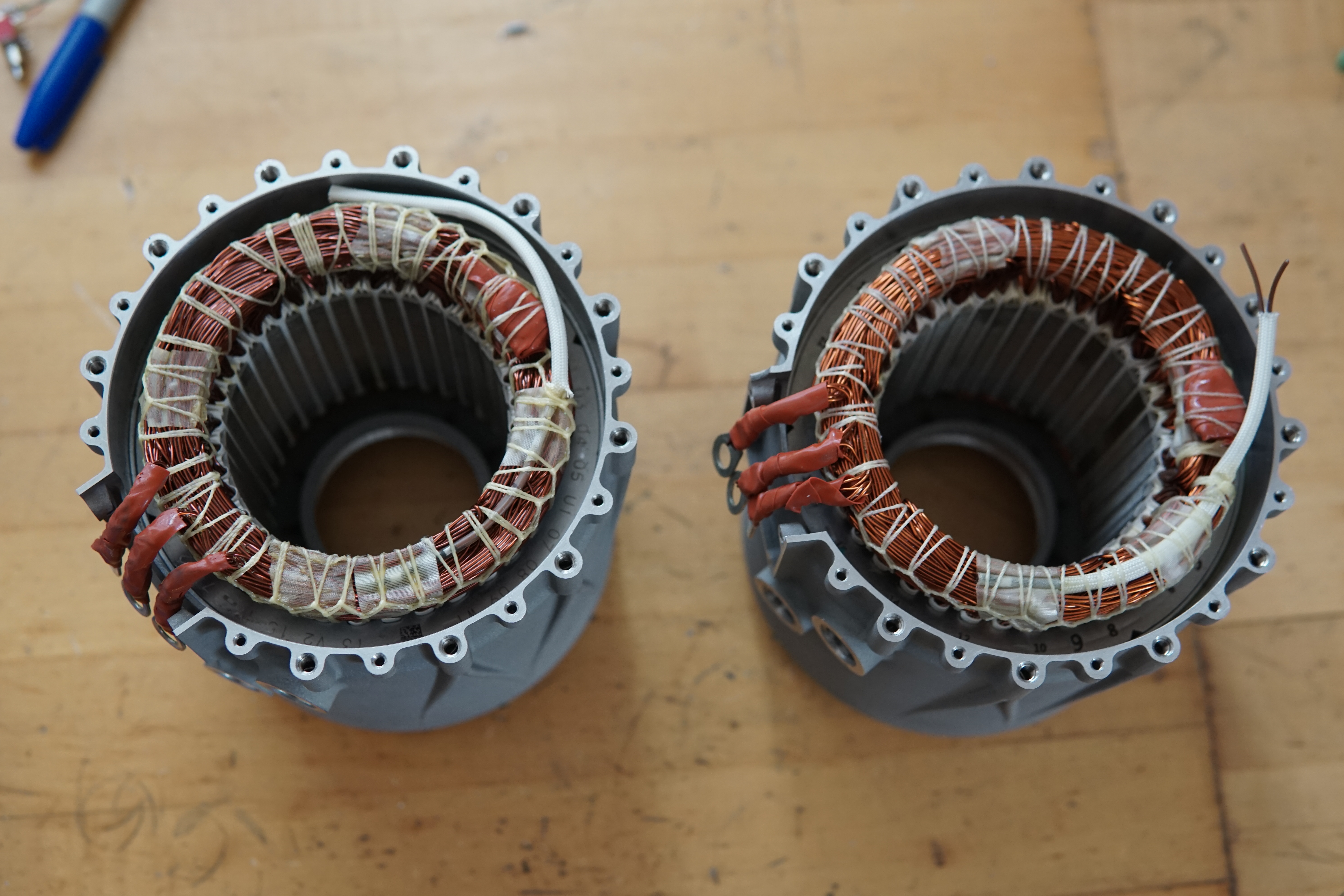
I got even more use out of the stator fixture for installing the stators. I added a guide rod to the fixture, concentric to the motor housing:
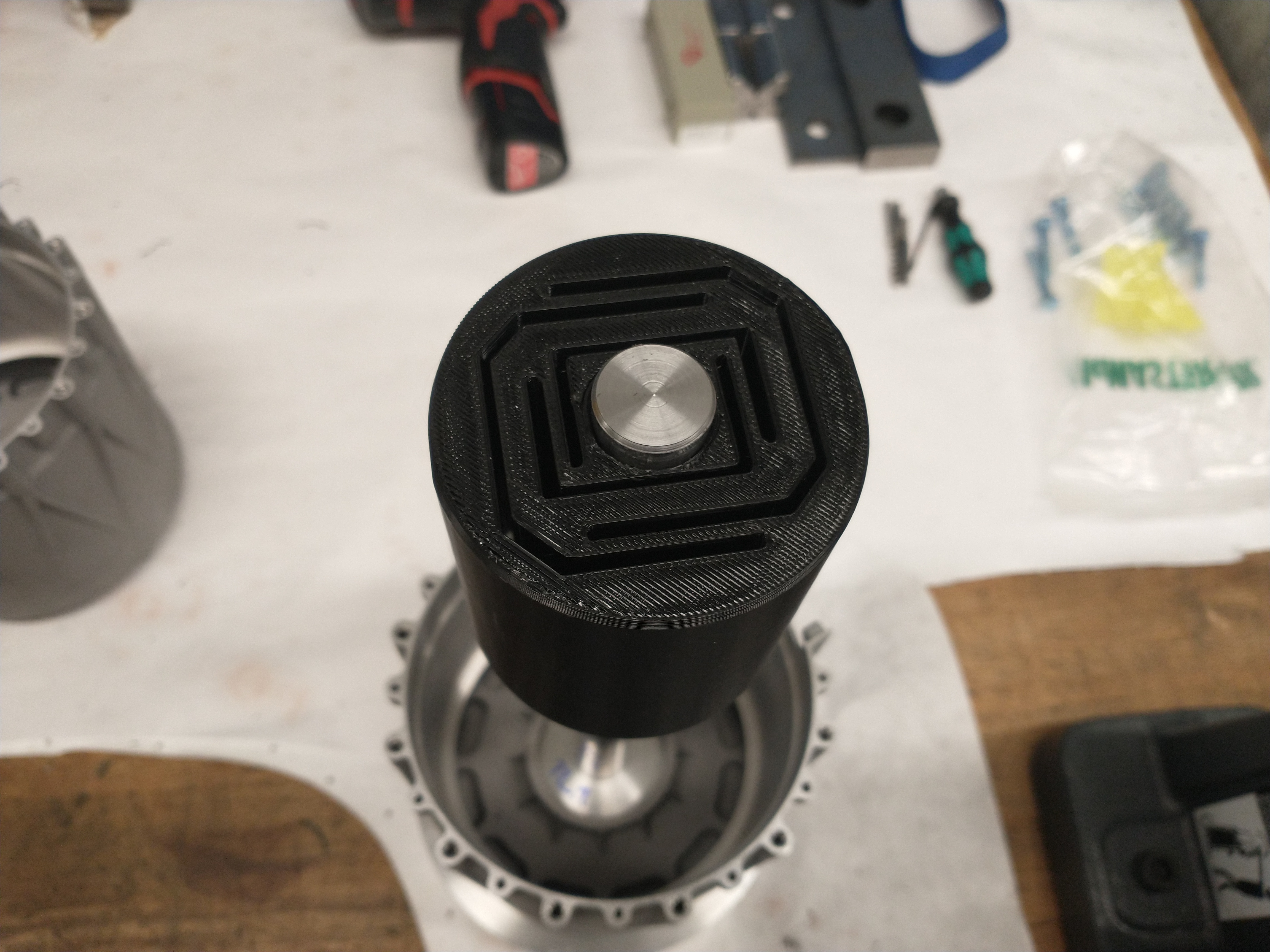
I 3d-printed a flexure to guide the stator into the housing - the flexure is a light press into the ID of the stator, and designed to be stiff in tilting but compliant in X/Y. This keeps the stator axis parallel to the housing axis, but lets the stator center itself on the housing bore:
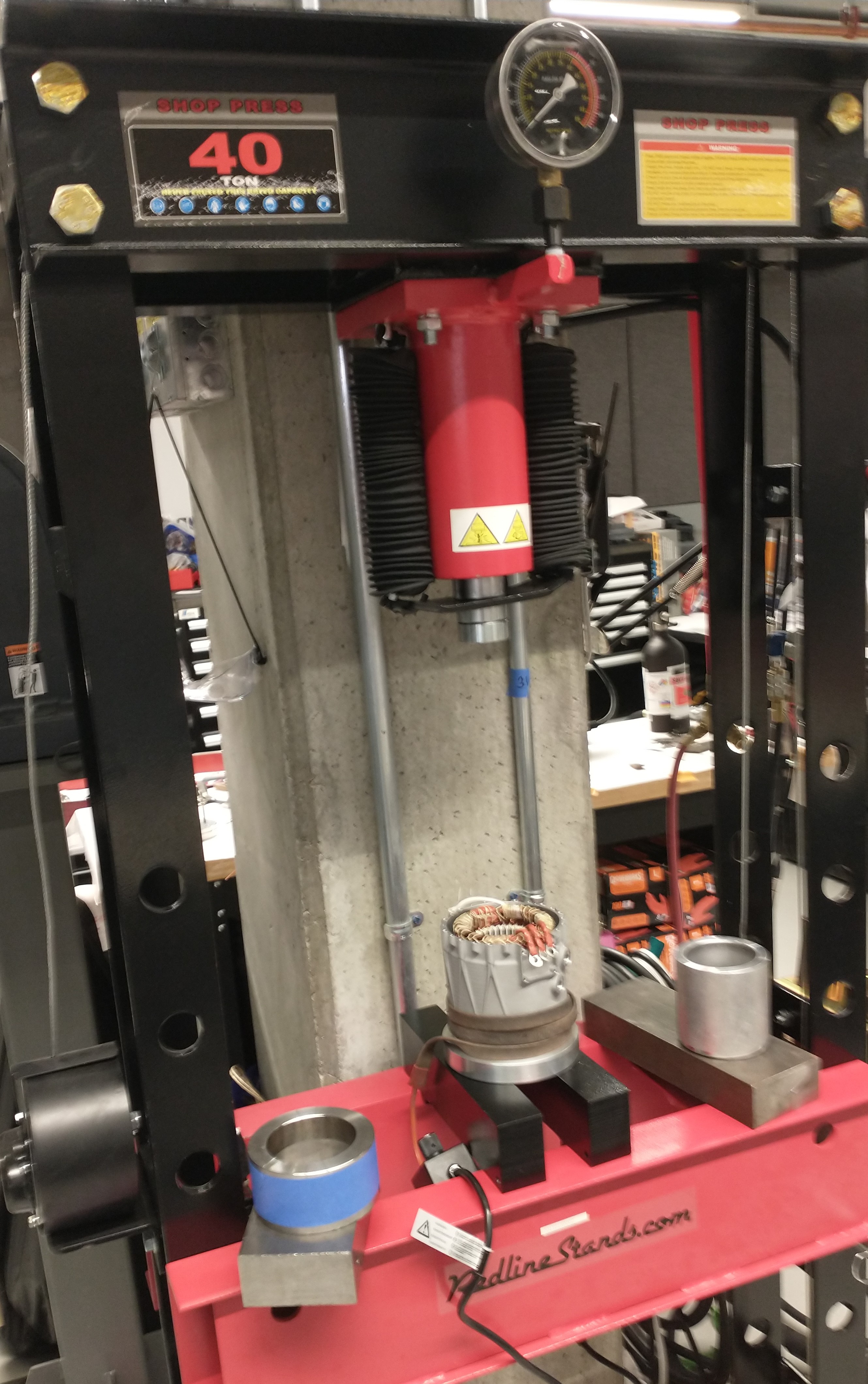
The stator was a light interference fit into the housing and secured with retaining compound. I heated up the housing to around 100C with a wrap-around heater to open up the housing and slip the stator into place. I did the assembly in a pneumatic-driven hydraulic press, I could send the stator home with the press if it got stuck half way down:
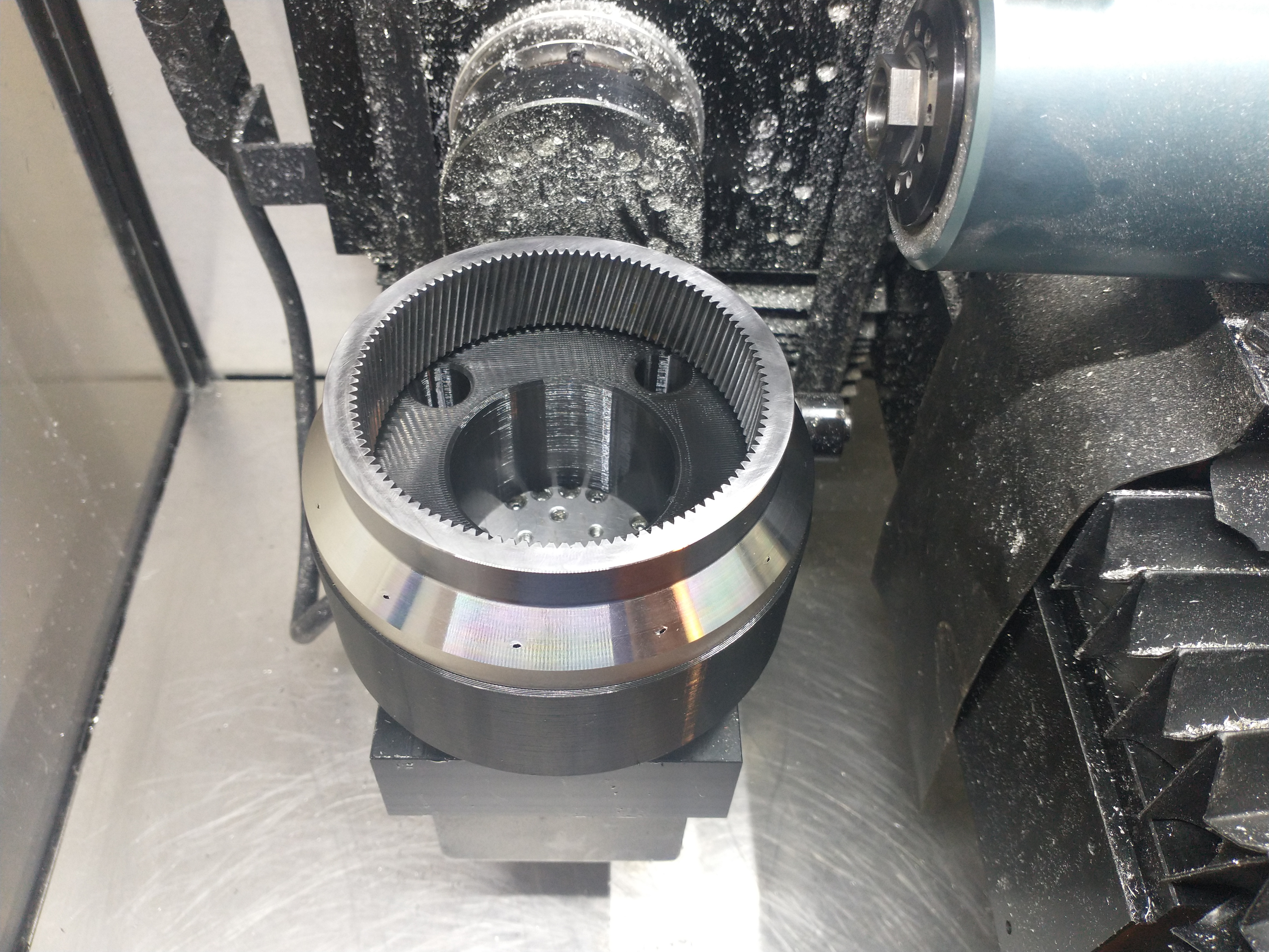
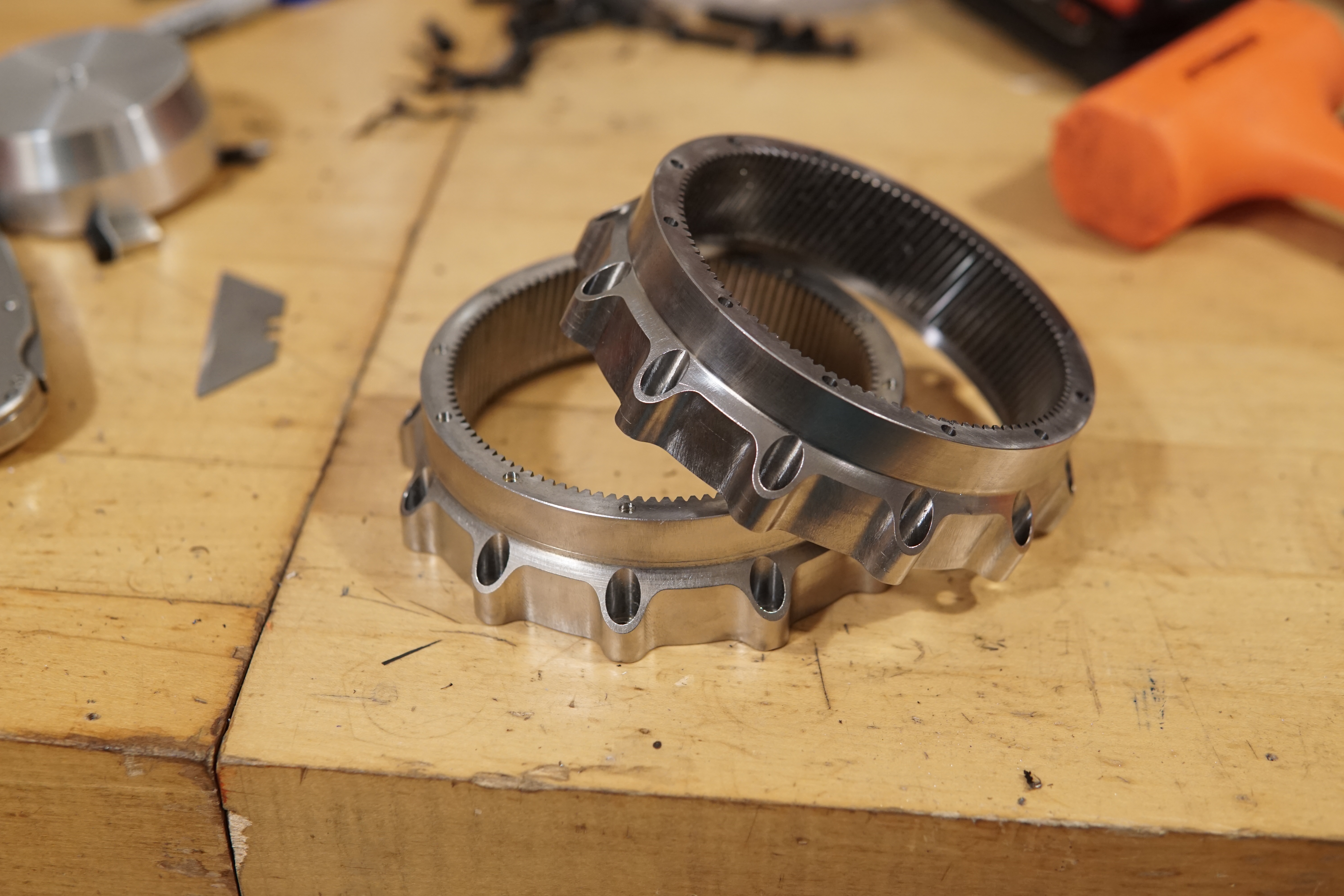
Both ring gears after some hand-tapping and deburring
Gentle warming with a heat gun and it slips onto the front of the motor housing:
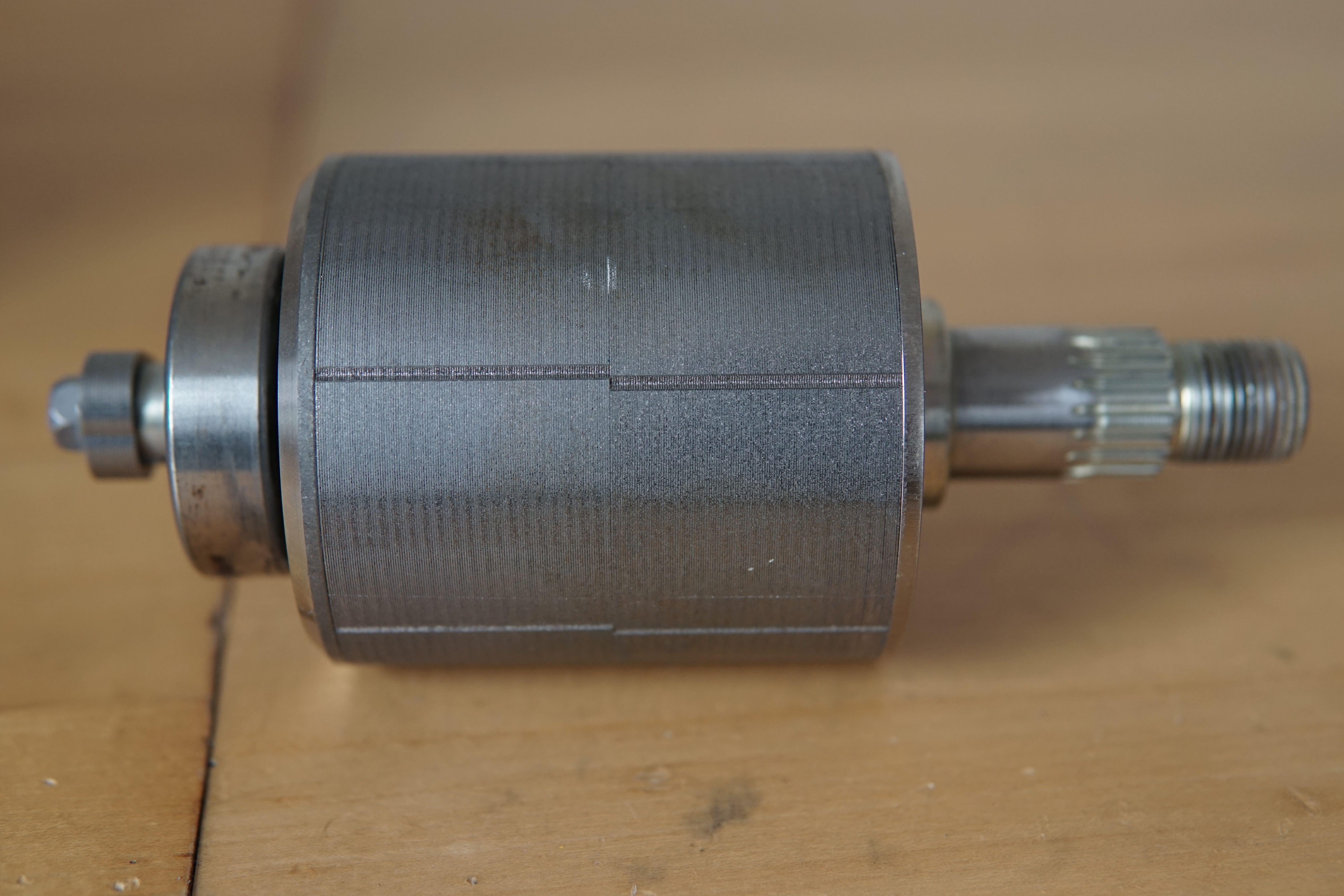
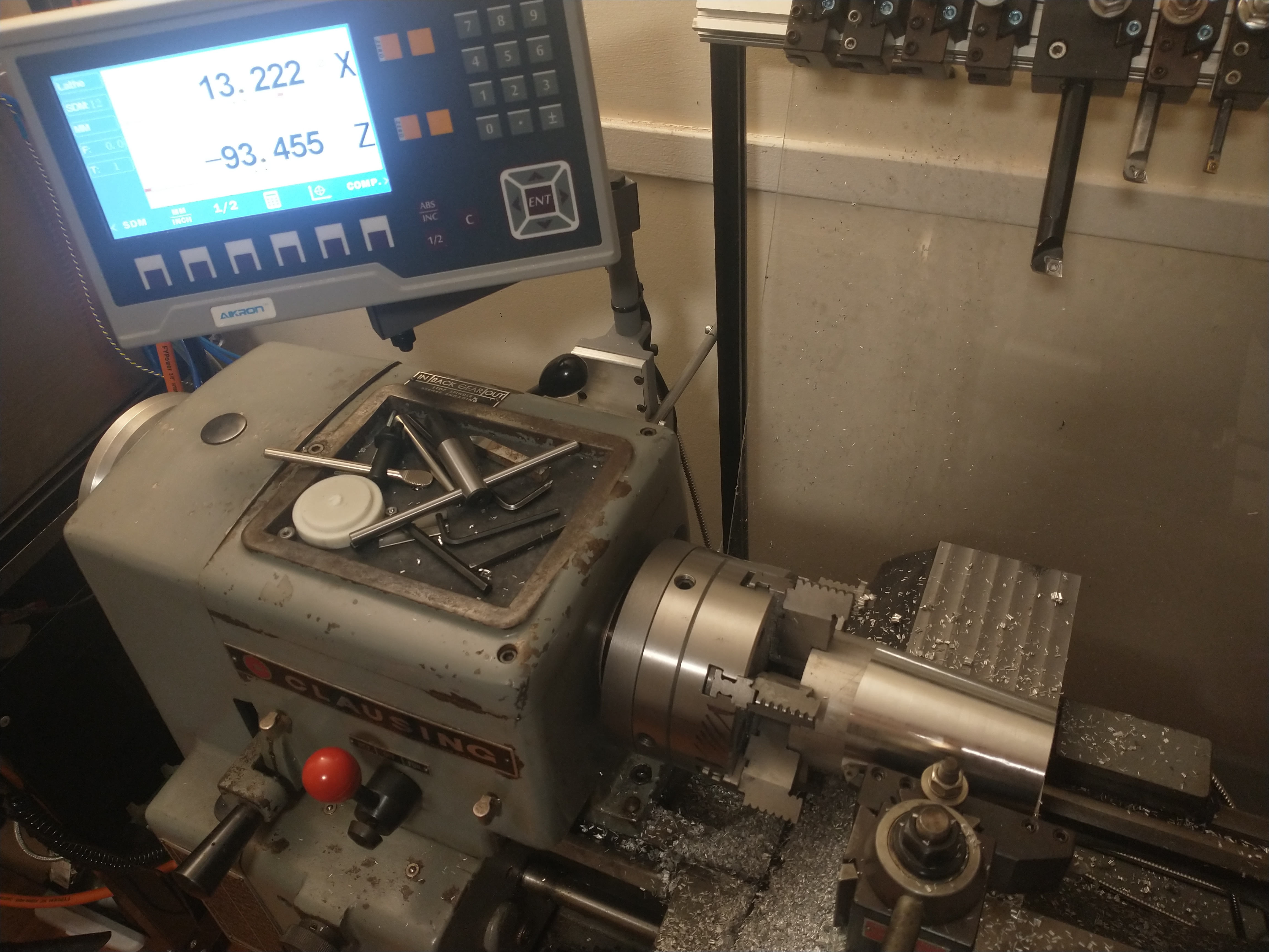
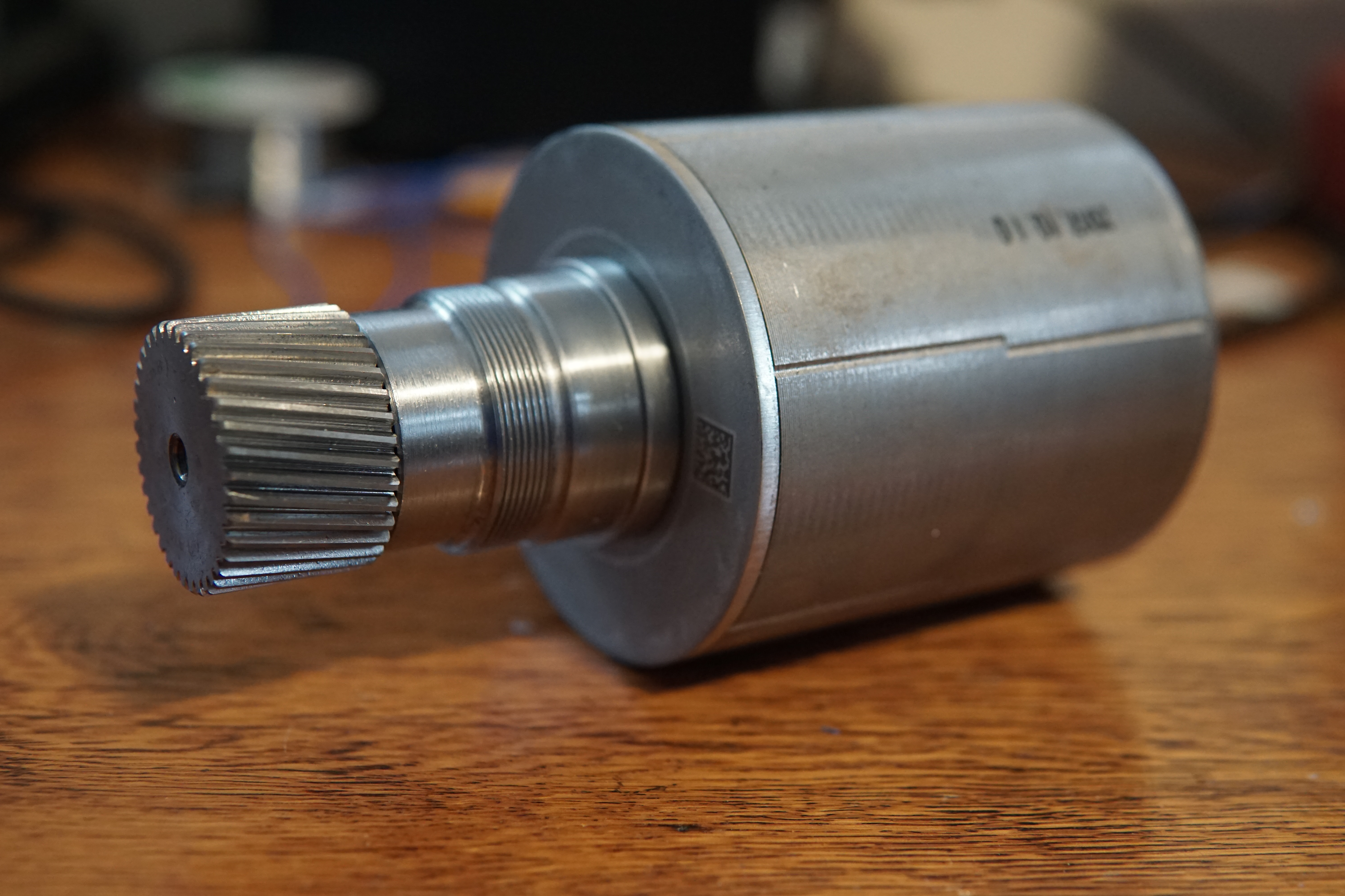
I made a new rotor shaft for the Ioniq motor to interface directly with the sun gear. These were turned out of 4140 HT bar (pre-heat-treated to ~32 HRC) on the Clausing:
 |
| I roughed with inserts for steel, but the polished insert for aluminum left a fantastic finish on light finishing passes |
 |
| Nice |
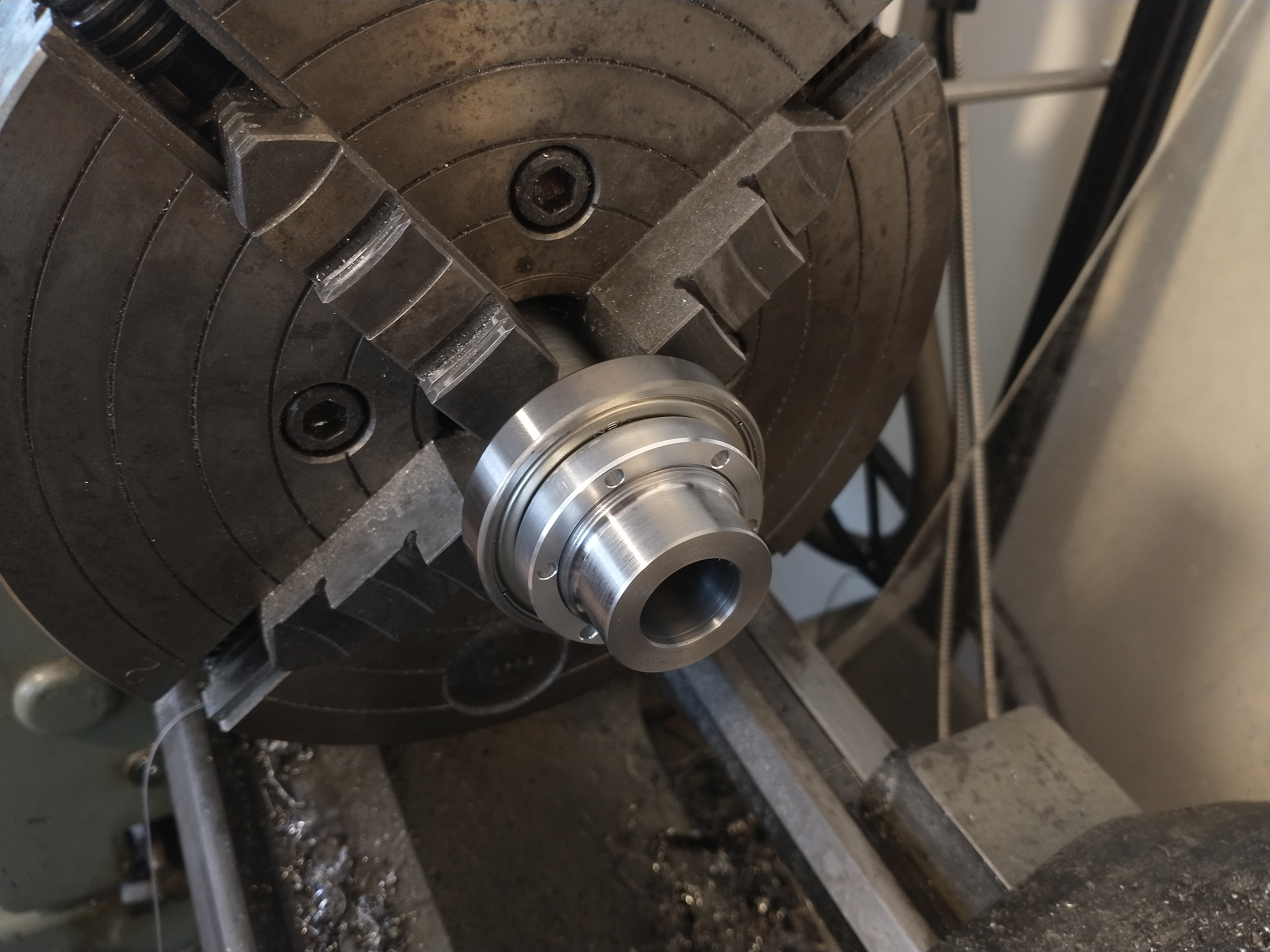
The front is threaded for a lockring that clamps the front rotor bearing:
Bearing and lockring test fit:
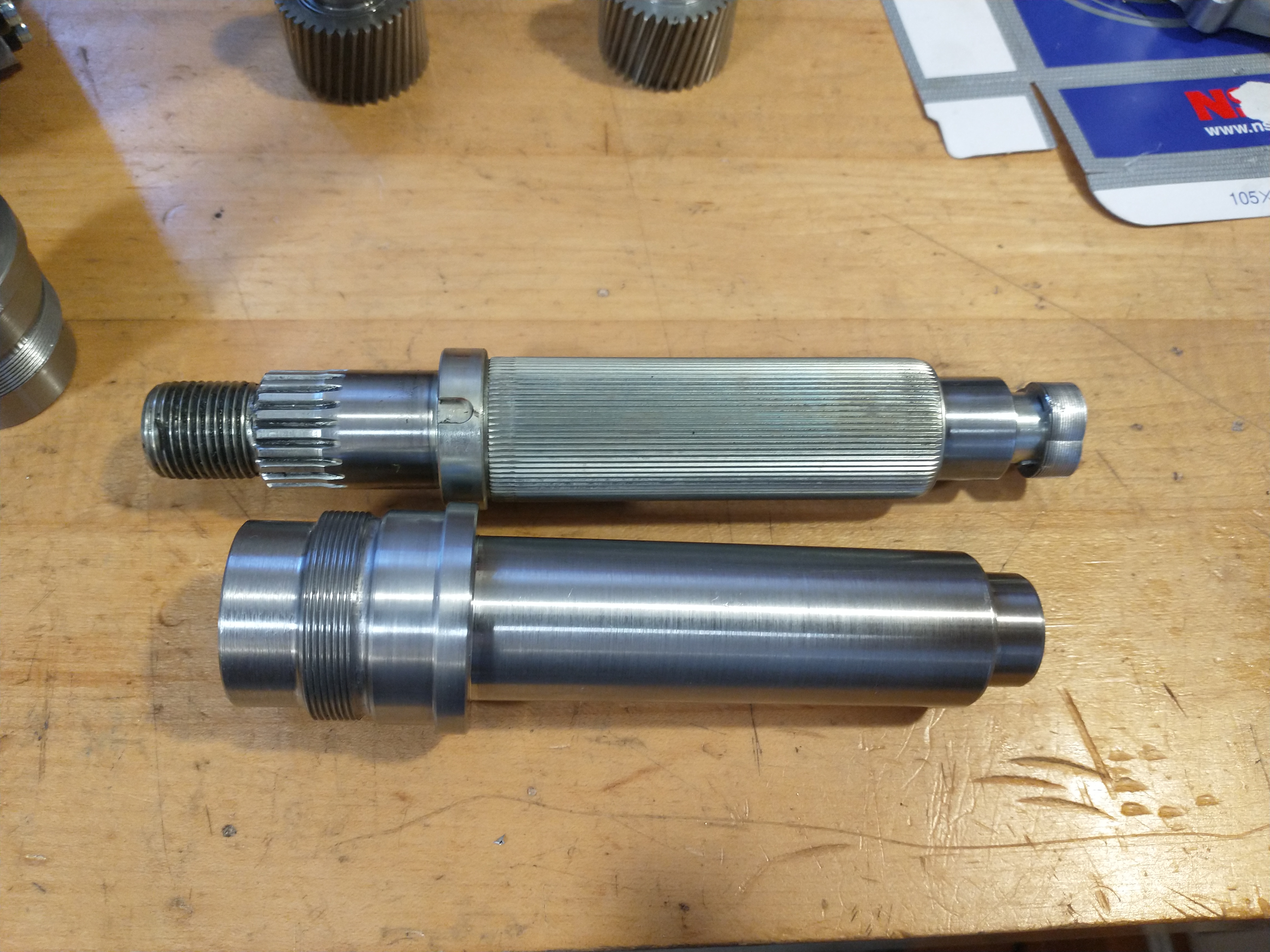
Here's the new shaft next to the original. The original used a straight knurle press fit to transfer torque from the rotor lamination stack. I went with a straight press-fit with retaining compound since it's simpler and not a super high stress interface.
The sun gear is held in with a heavy press fit + retaining compound. I copied the amount of interference from the original gearbox shaft:
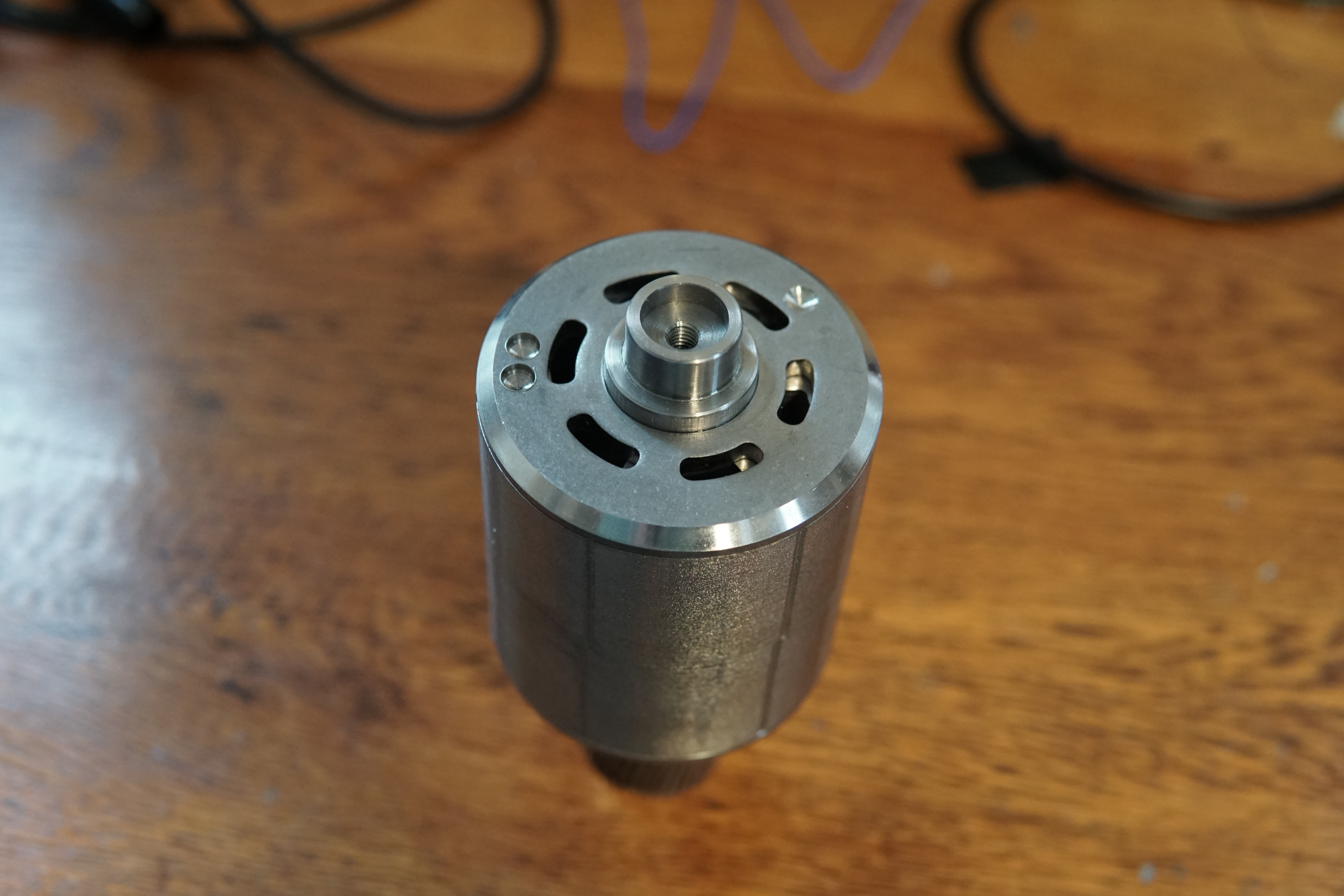
I put a generic M6 tap + 15mm bore interface on the back of the rotor for encoders. Eventually I'll probably switch to a magnetic encoder, but right now I've attached the stock resolvers since that's what the kart's electronics are set up to deal with
 |
| I may get the rotors re-balanced, apparently it's not to expensive and the balance has probably changed with the new shafts. |
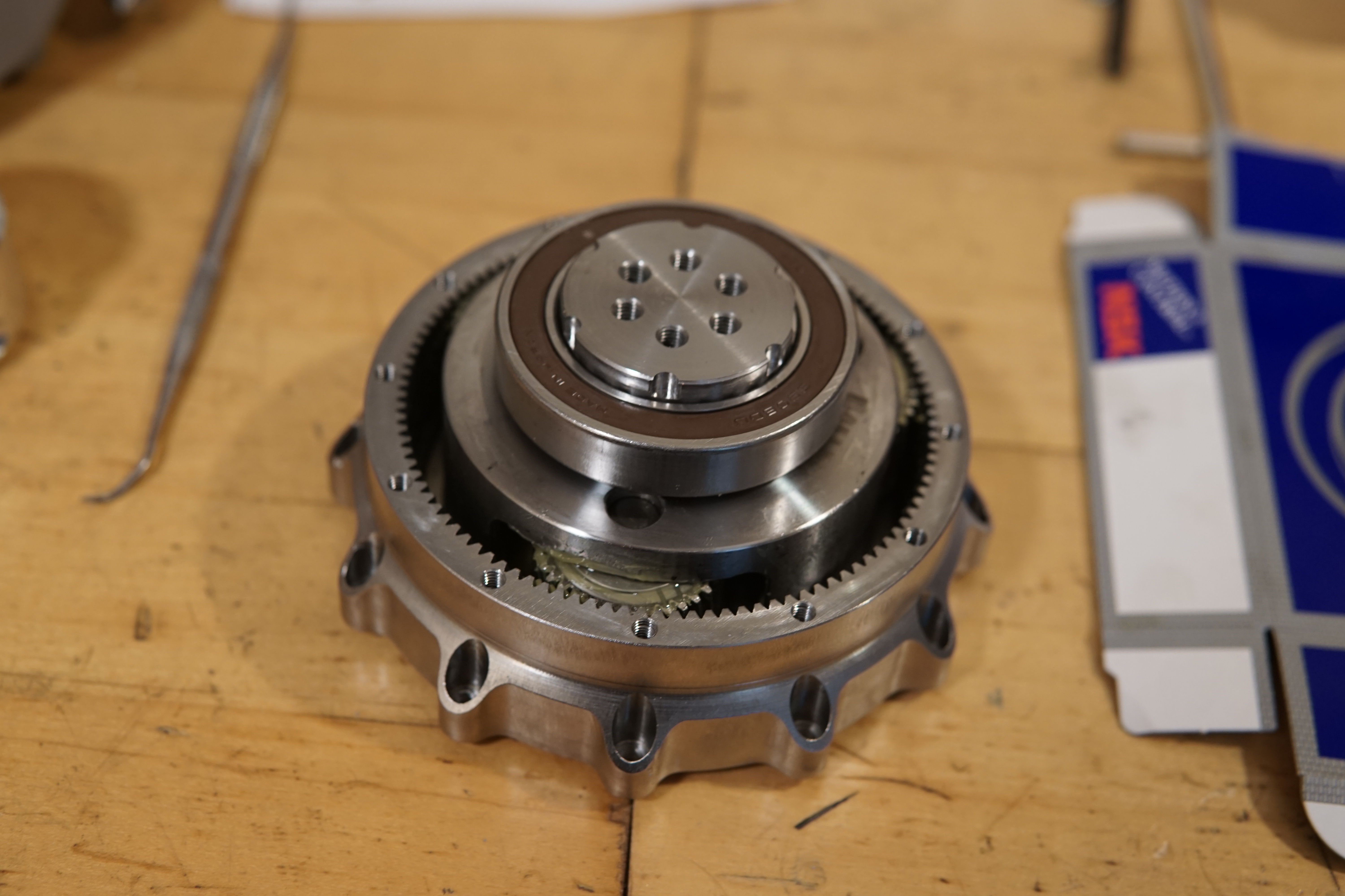
Rotor installed in the drive unit:
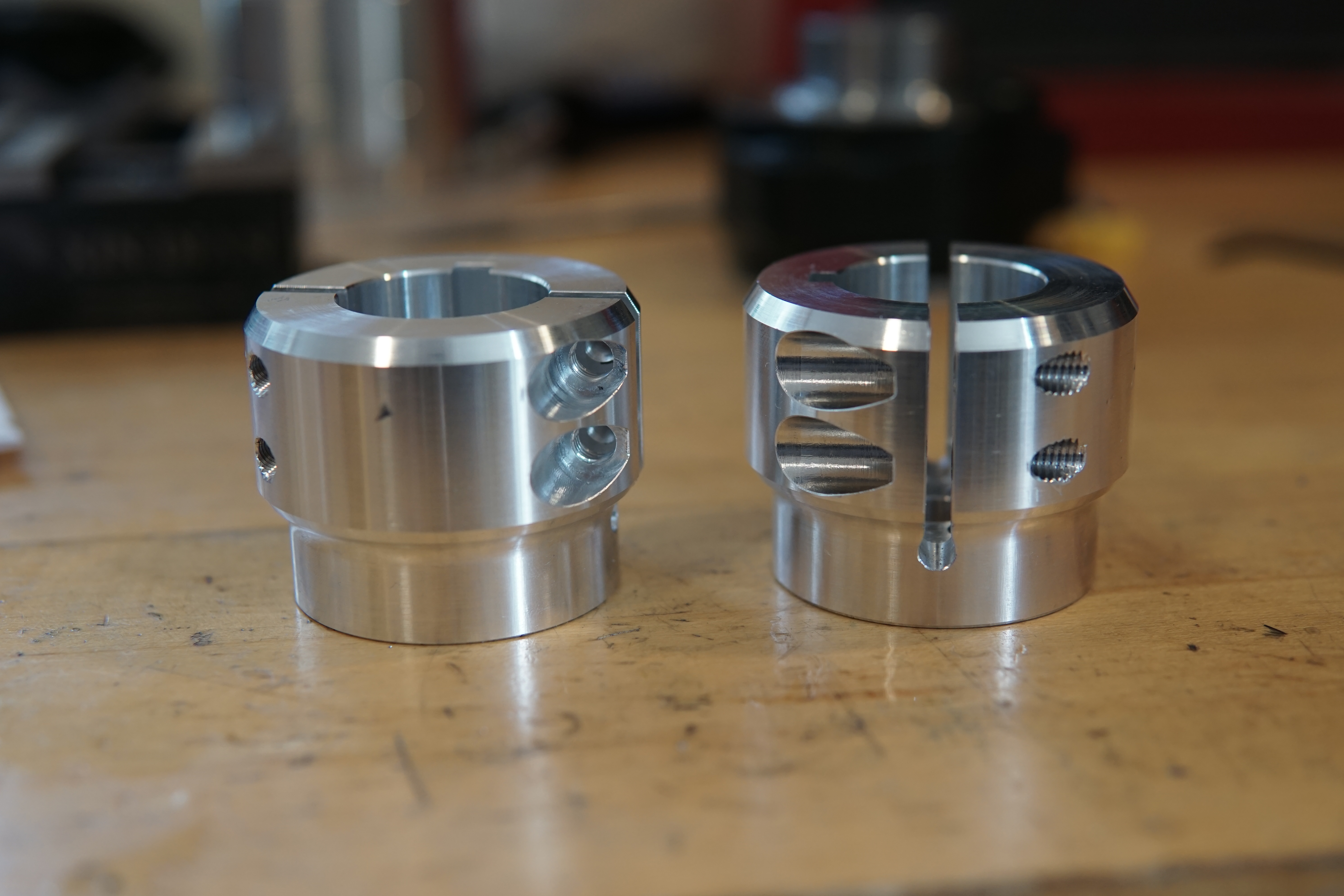
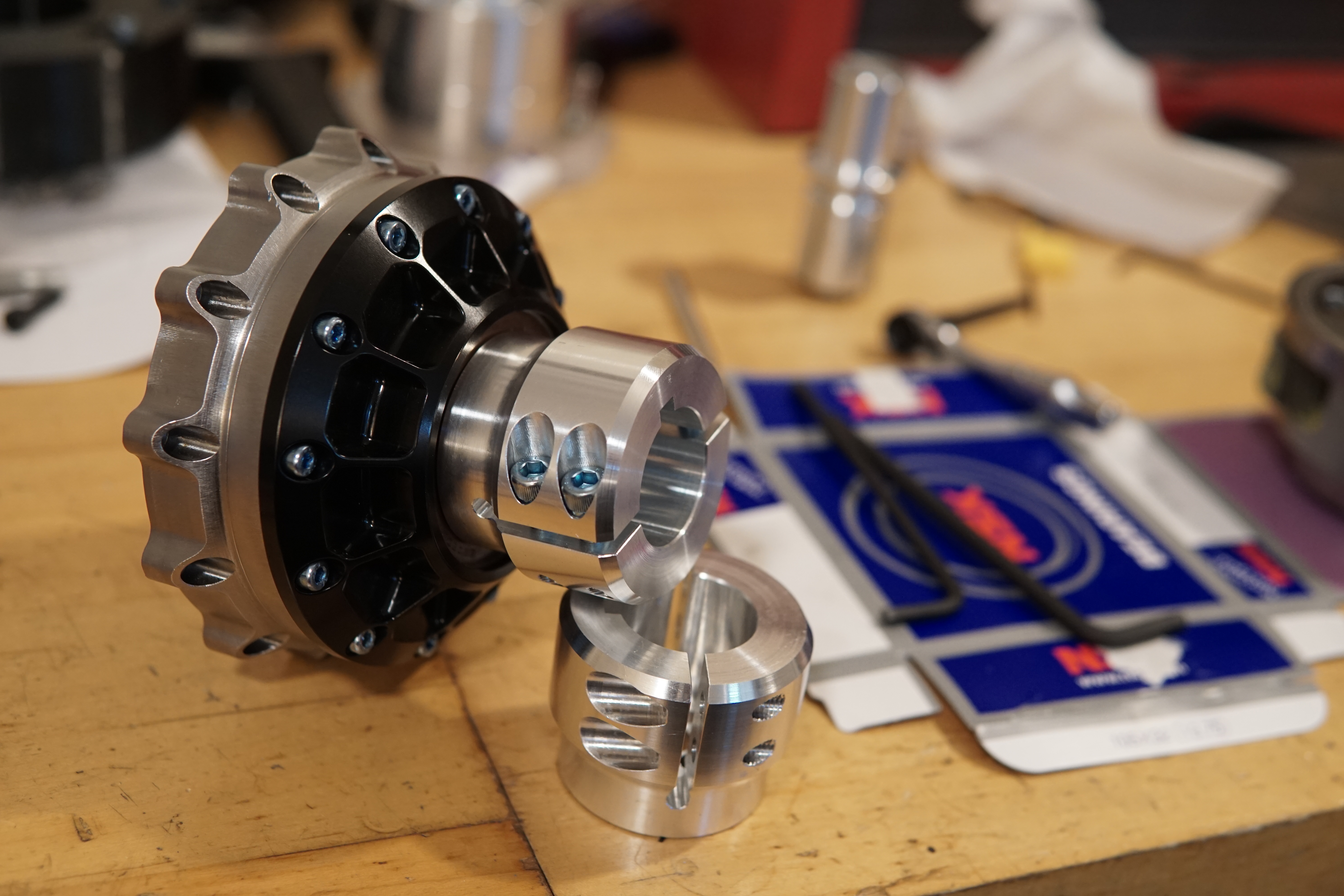
The output of the gearbox clamps directly on the keyed go-kart axle. I shortened the stock output shaft on the planet carrier, tapped a hole pattern in it, and machined some clamping shaft couplings that bolt to the face of the carrier. This part does double-duty clamping the inner race of the bearing on the front of the gearbox
 |
| Planet carrier milling. Planets taped up so swarf doesn't get in sensitive places |
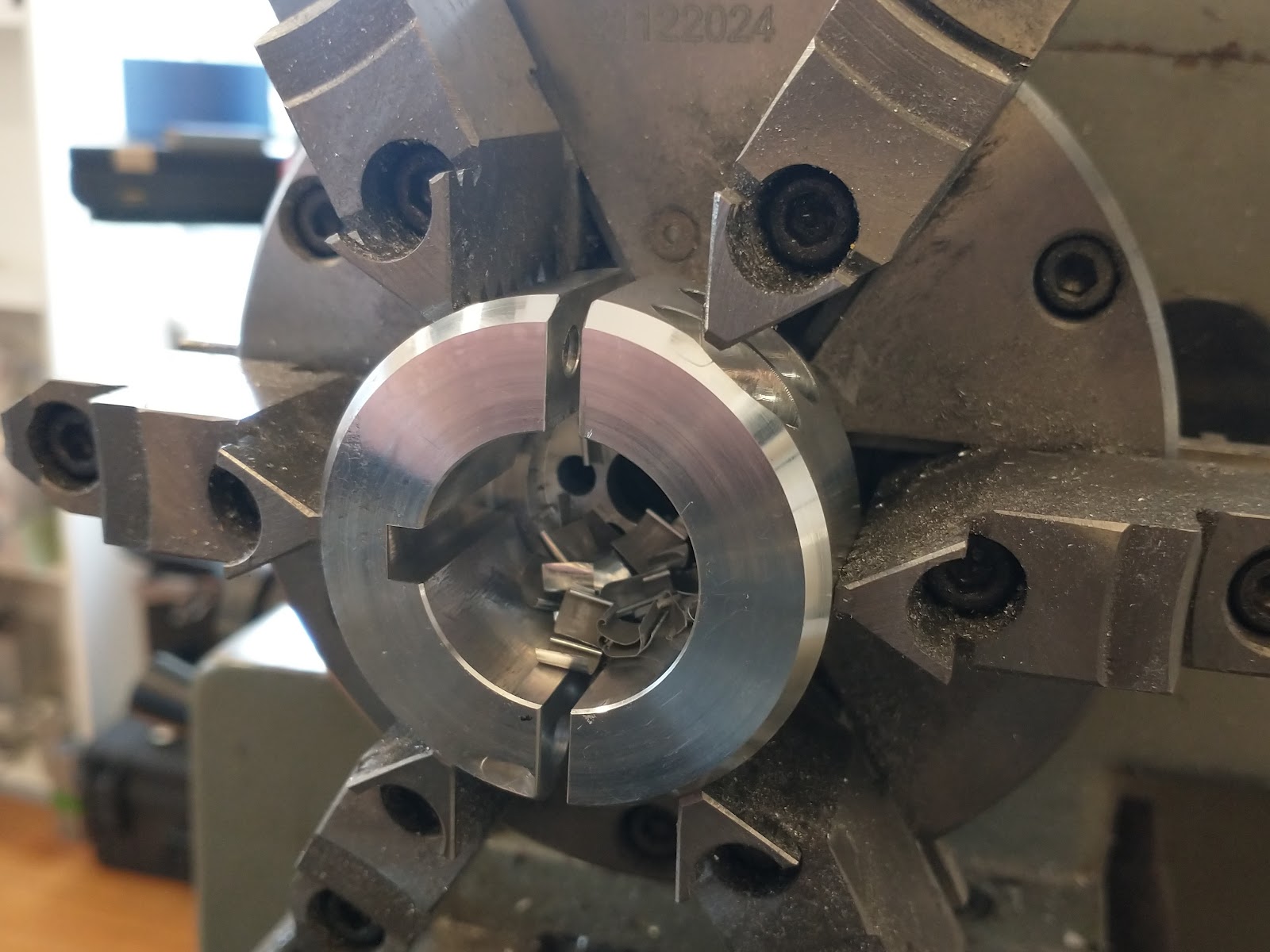
I broke out my old lathe-broaching tools and single-point broached the 6mm keyway on the lathe:
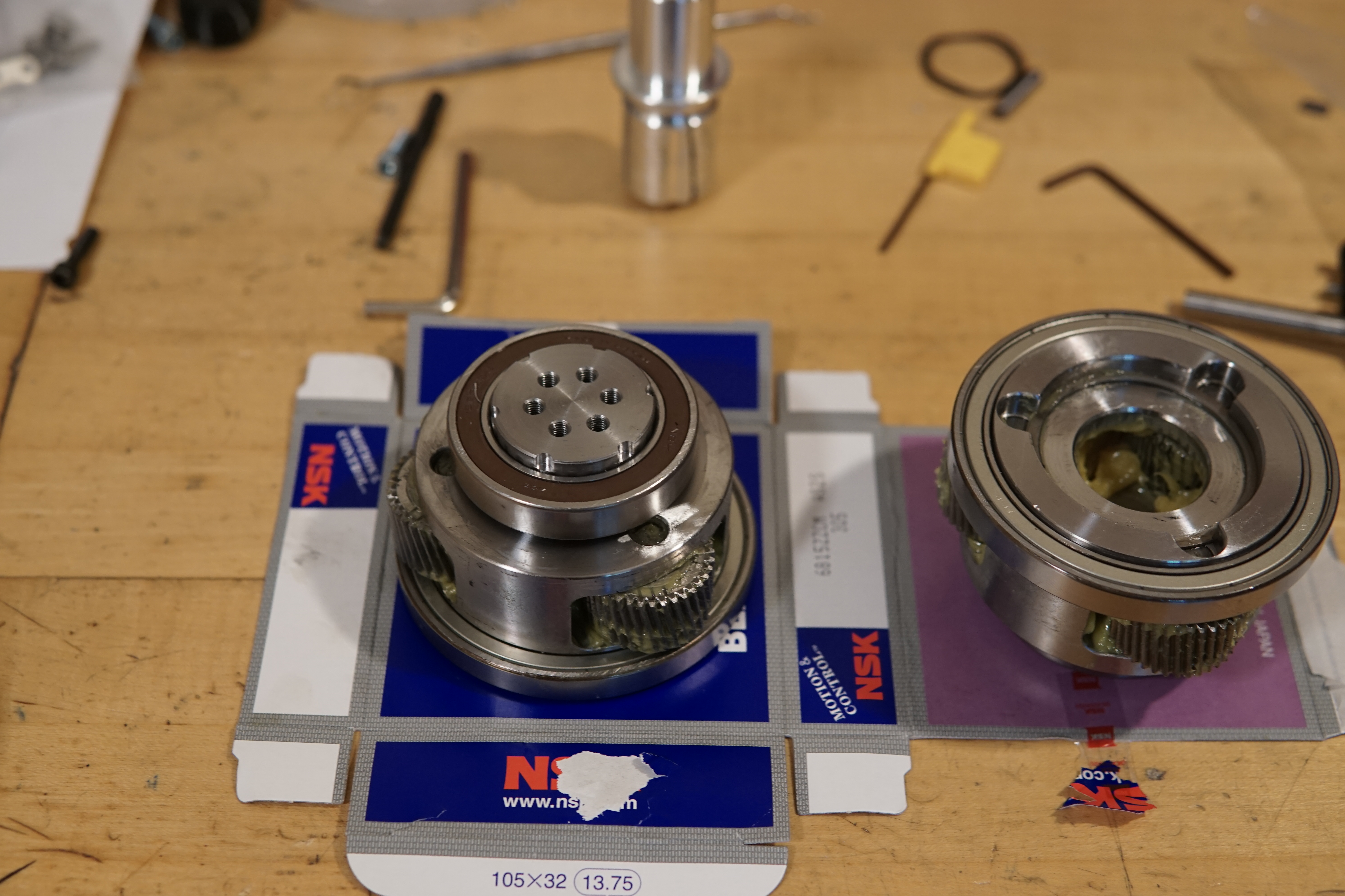
Gear box re-assembly with new bearings. I splurged a bit on legit NSK brand bearings:
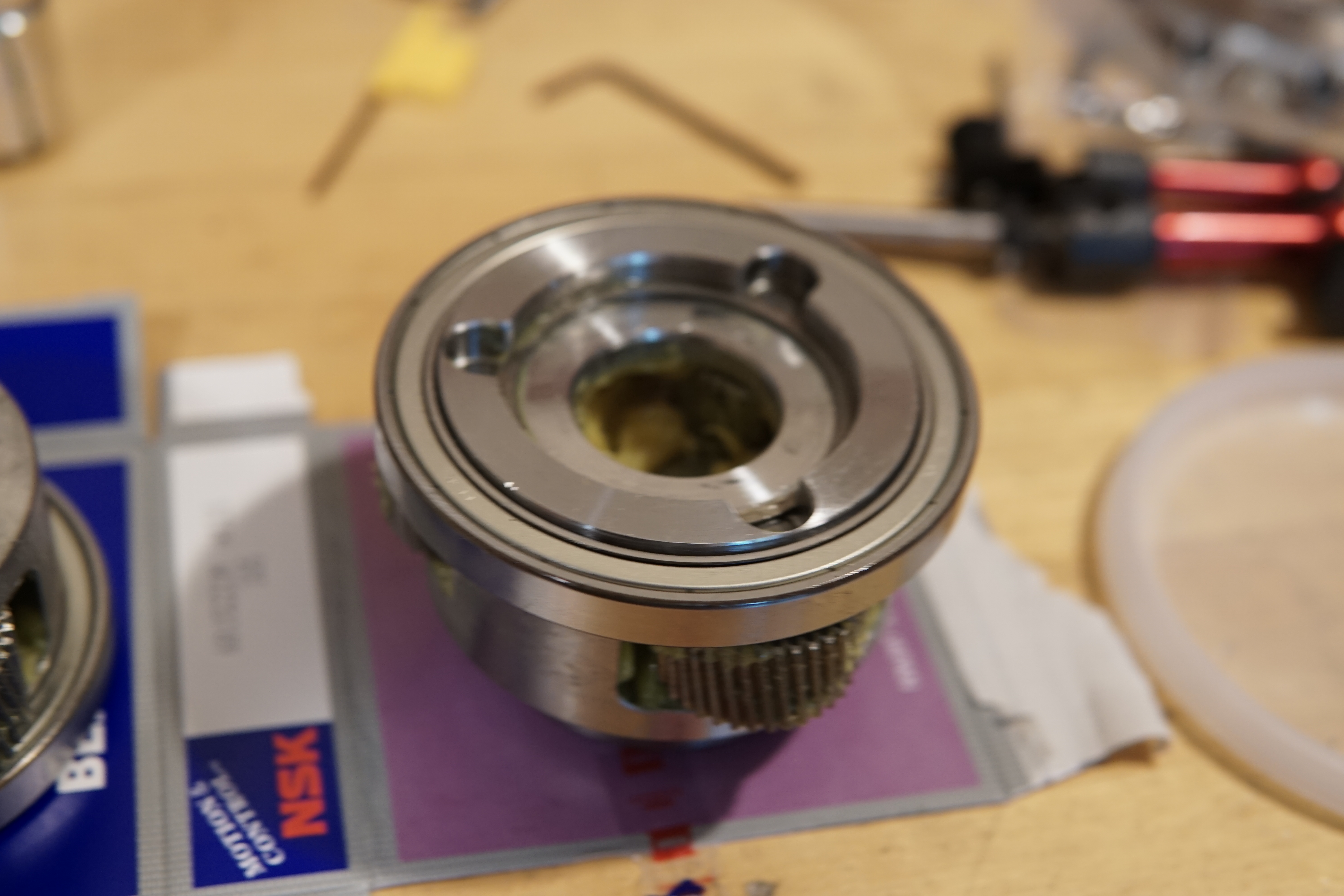
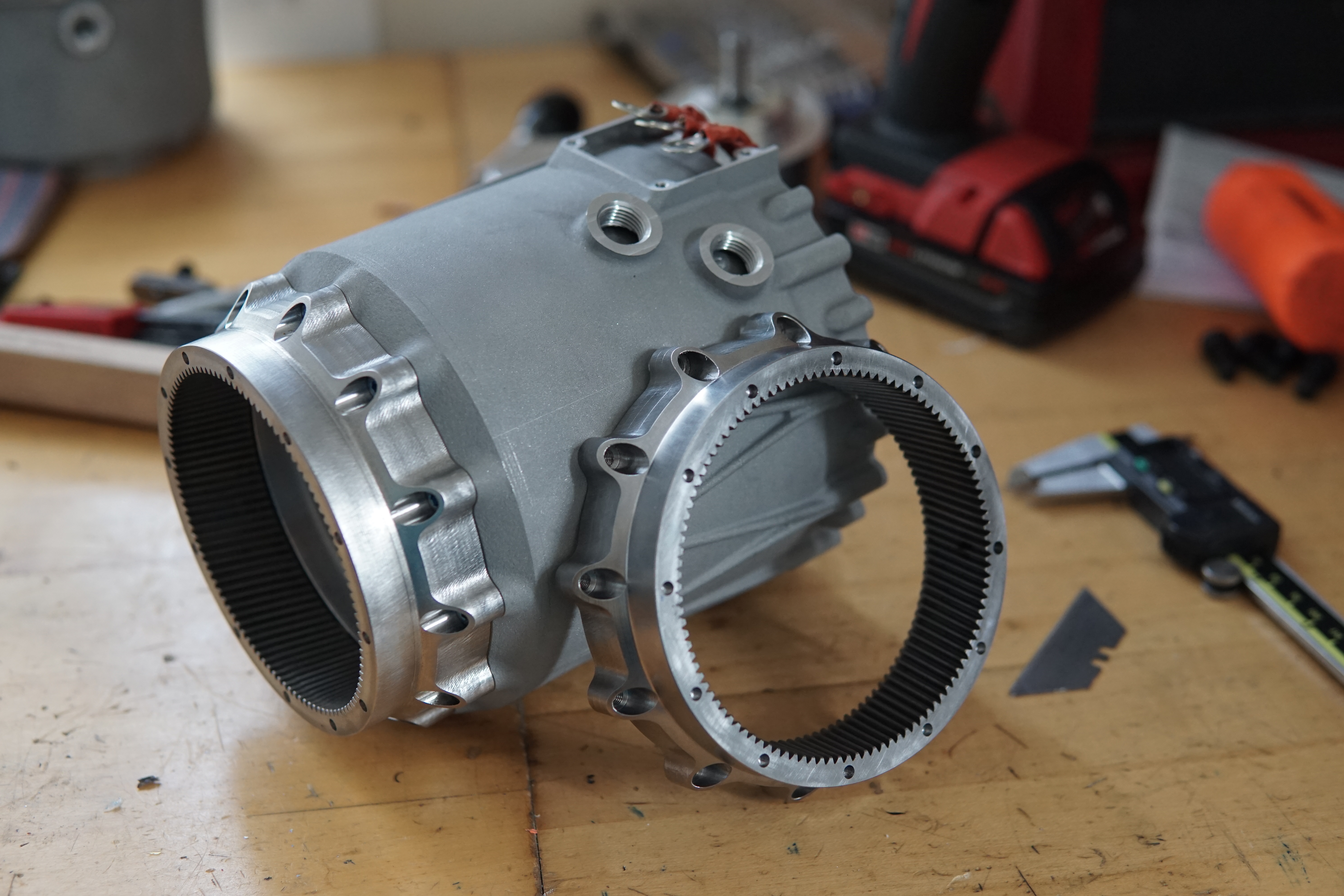
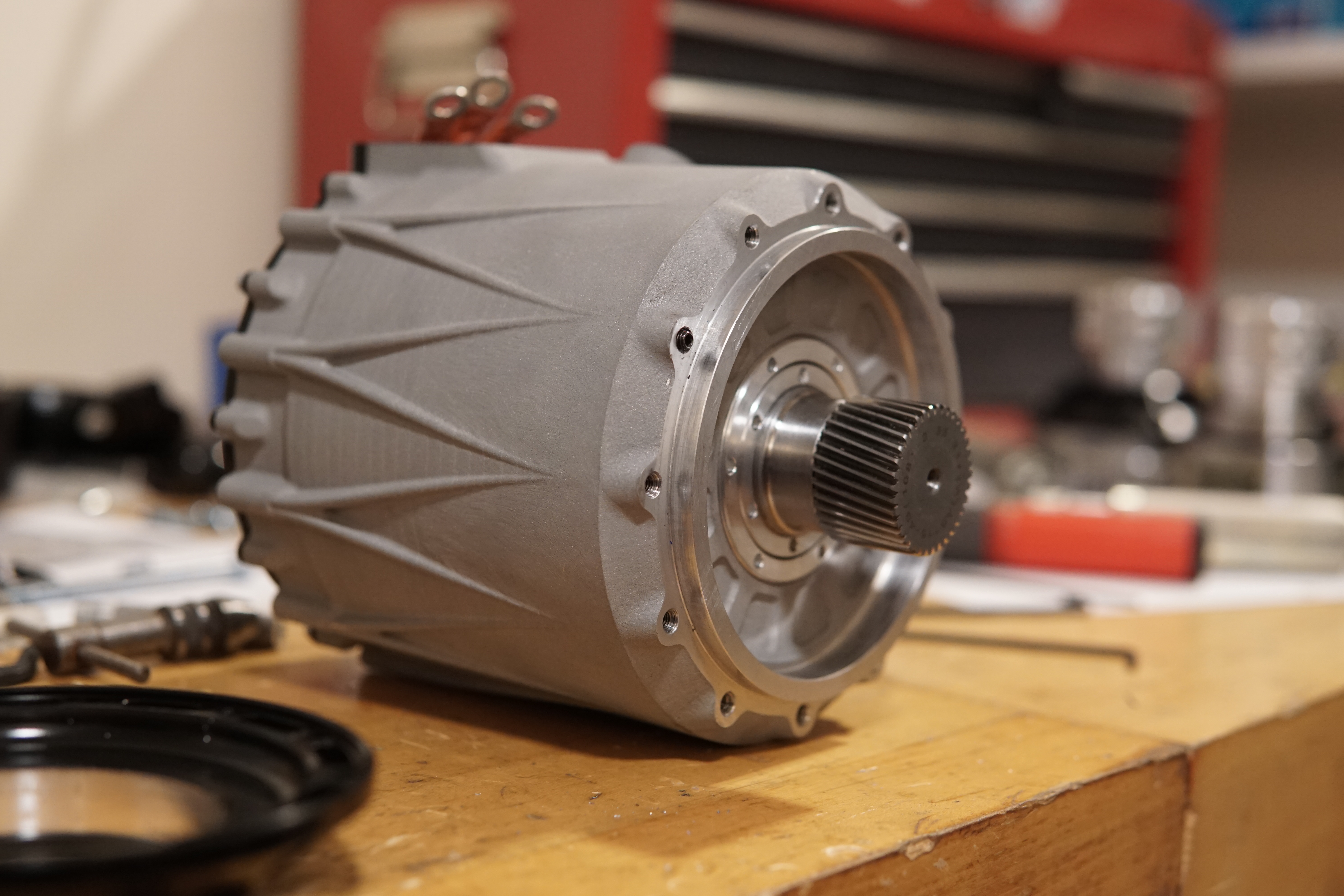
Gearbox assembled with the new front plate (sent out to have this machined and anodized black) and output coupling:
Comments